Having connected up the XJR dashboard display, I managed to get the Mileometer working showing the previous XJR milage. However it also displayed AIRBAG and FLUID repeatedly so not so good. The FLUID was straight forward to resolve by connecting the appropriate wire to ground. I misread the circuit diagram and thought the AIRBAG signal needed to be at +B. Having temporarily connected the wire to a +12V battery feed it still said AIRBAG. I tried grounding the wire, still AIRBAG! I tried adjusting the voltage to the wire using a variable resistance box but still same AIRBAG error. I took the display board out of the assembly and studied it closely.
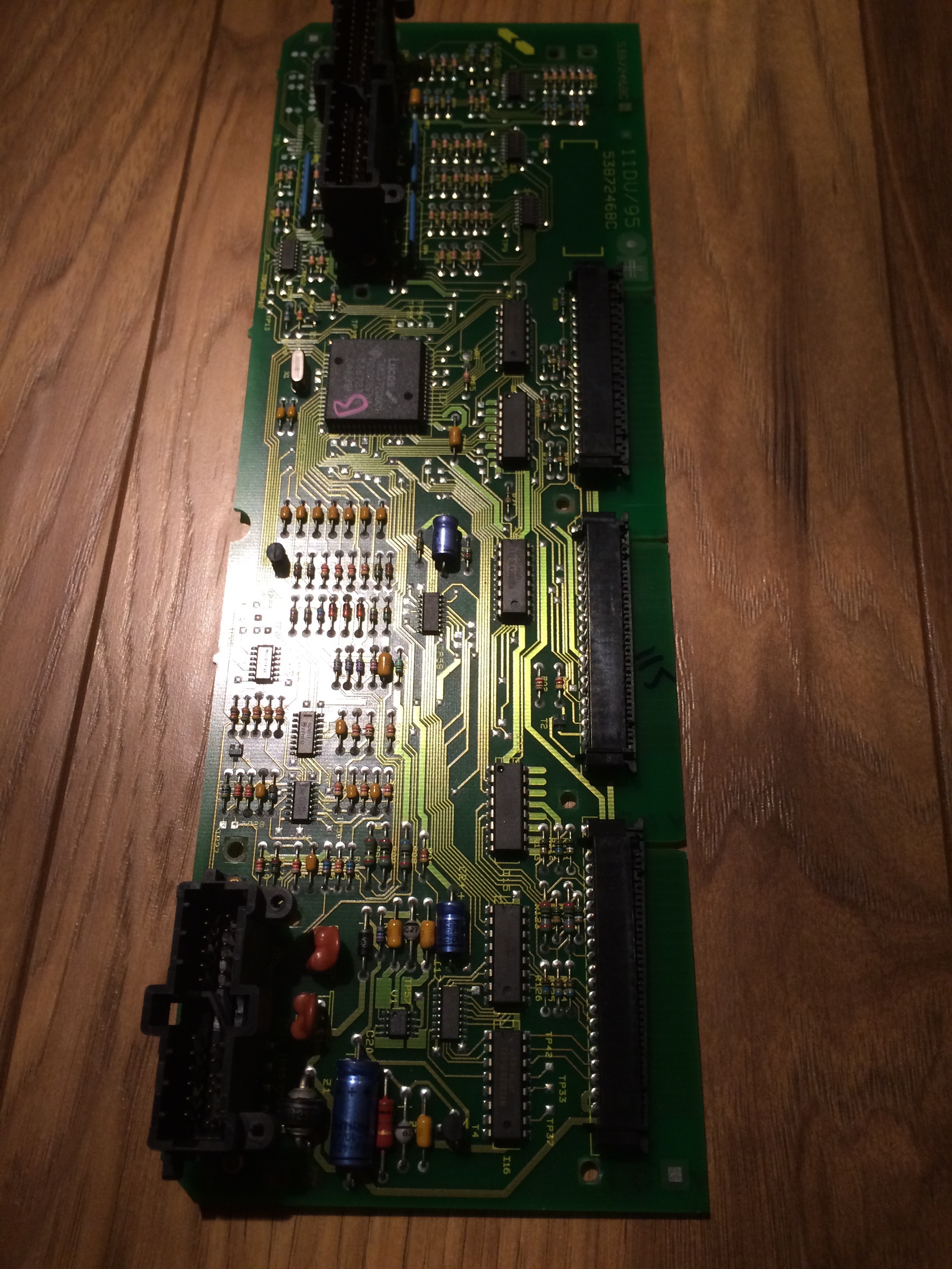
Instrument Display Board
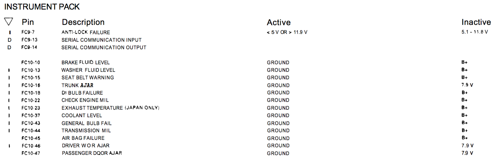
I traced the input wire (pin 45) to an input on a surface mounted integrated chip with HC151 printed upon it. This is an 8:1 multiplexer chip. My guess is that the inputs are sequentially scanned and the outputs read to determine the status of the input signals. What that means is that if the chip is faulty (possibly damaged by me directly connecting 12V to the input?) then I cant just tie the outputs to one state as I will get other errors flagged as well. I am not sure this is the problem because the detail in the circuit diagram does say it is either ground or +B. The input circuit seems to have the signal going to the middle of a pair of resistors so the input voltage would be split in half anyway. The spec of the chip states 6V maximum input which is a little close, especially as my old XJS with an AJ16 engine used to run at 13.8V most of the time!
Pin outs from the manual
I have ordered a replacement IC (or 5) just in case. They are not expensive but I will have to wait a few days for them to arrive. The suspect chip (11) is highlighted by the red arrow in the picture below.
Instrument Display Board showing the suspected chip arrowed in red
The image below shows the location of the input signal, the +B and the ground points and the signal feed to pin 12 of IC 11
The Engine is back in again, hopefully finally this time 🙂
Firstly, sorry the site was down yesterday. Something wrong at the ISP.
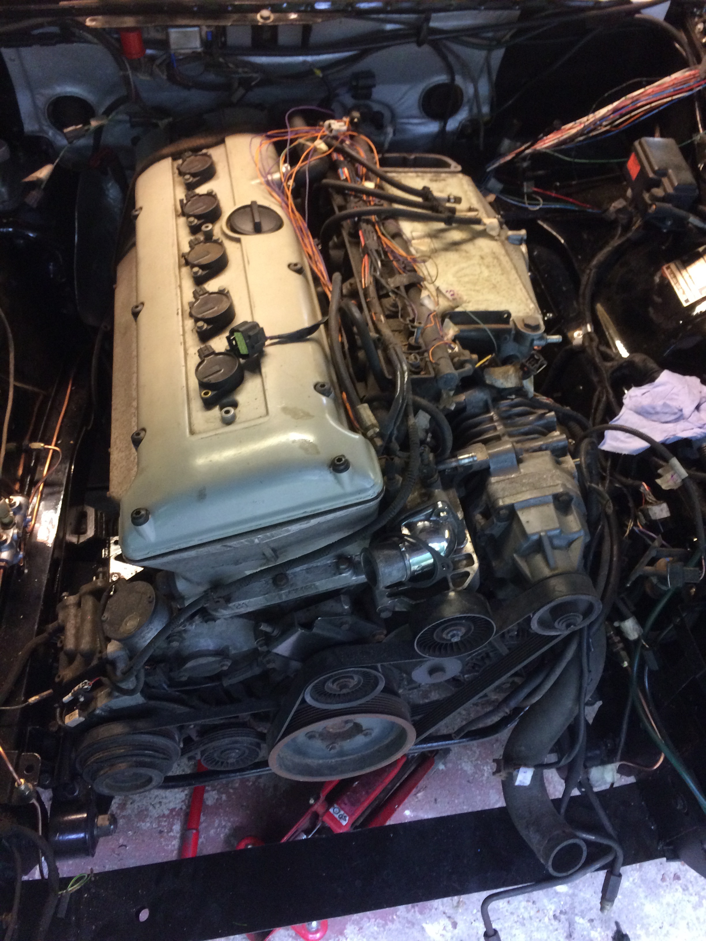
I had a week off and managed to spend a day in the garage. I set things up ready to install the engine and just as I pushed the engine & hoist a few feet out of the garage to enable me to push it into the engine bay it started raining. Well obviously it was time for a tea break so I left it like that for about an hour and then proceeded to get the engine back in the car. It is now sitting on the engine mounts and the gear box is supported underneath with wooden blocks. I do have a slight problem now as I cant get under the car and into the pit without moving it and obviously can’t move it with the gearbox on blocks. I will have to support the rear of the engine to allow me to move it and carry on fitting the gearbox mounts in the new location.
Engine in placeSupercharged AJ16 engine waiting to be put into the Series 2
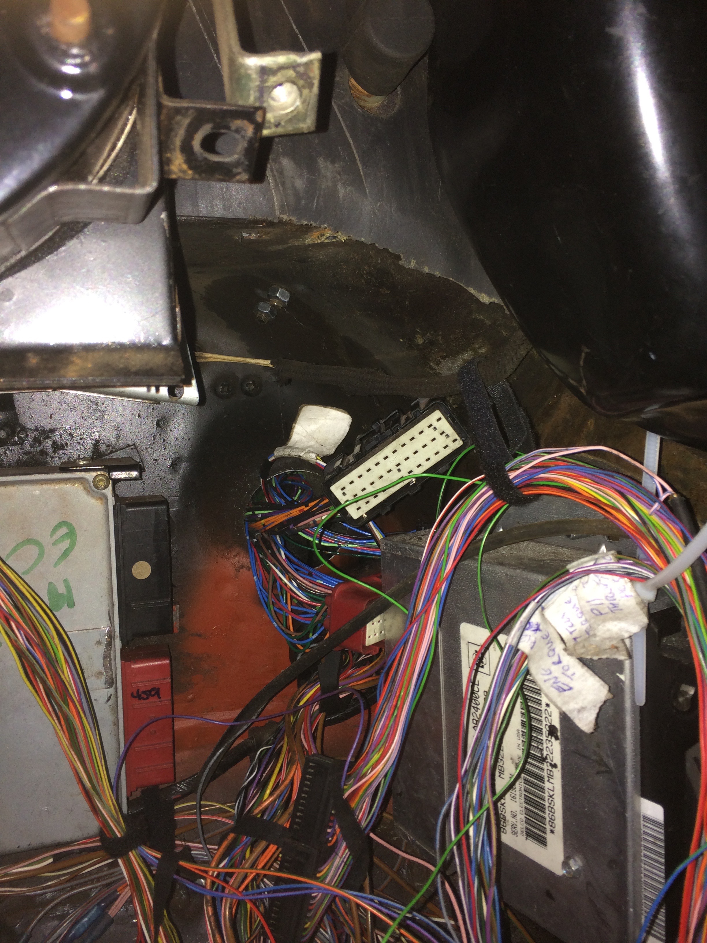
The engine loom was pushed through the hole in the bulkhead as you can see below and then I did a little debugging of the electronics.
ECU plugs poking through the hole
I connected the power, checked for no smoke 🙂 and looked to see if the ODB2 port was working.
OBD2 wireless module powered up, app on iPhone could not see/connect to the ECU
Unplugged the ECU plugs and checked for 12V (+B) – not present
Checked the ECU power relay was switching on – it was not?
Checked the power in the new fuse box in the engine bay and discovered the relay in the fuse box enabling the “switched” power was not being energised
Followed the cables back because this was working a while ago and discovered the 48 pin connector I built into the bulkhead was not connected together fully.
Fuse box Relay was still not being engaged
Traced this back to the cable I was using for testing was not finally connected to the relay I wired up. The S2 ignition switch switches its outputs to +B when in each position. All the ignition switch positions on an XJR switch the associated output to ground. This means I need relays to convert the +B outputs to a ground signal to feed the appropriate signals to the various control units.
Wired up the correct cable to the relay output and now the Engine Bay fuse box is alive!
reconnected up the ECU plugs and now the ODB2 module/iPhone can talk to the ECU – hooray 🙂
Gave error code P1620 which looks like immobiliser error
Ok now I know the iPhone app will talk XJR I will purchase the full app and update you on further progress.
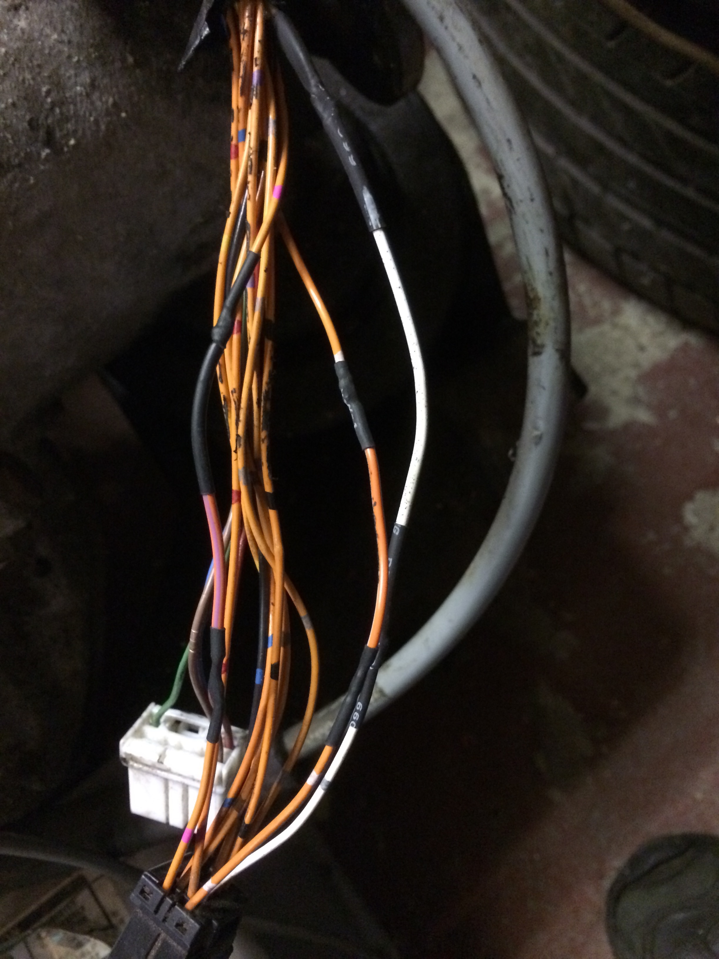
Another common failure, especially when removing/replacing the gearbox is damage to the cable loom. I had noticed the damage to my loom while moving the engine/transmission around the garage. There was at least one severed cable and a few more that were badly compressed which would lead to a failure late on. The first image shows the broken wire and if you look closely at the orange wires you can see a couple have been damaged too. I cut out the damaged area and inserted suitable replacement wires. The connections were solder jointed and then covered with heat shrink tubing to protect the joint. Finally I used some loom tape to protect the complete loom.
White & Slate wire cut through plus some damage to the Orange wiresRepaired WiresRepaired loom – Final protection with tape
I have been working with HortonWorks recently and they wanted to see the installation process of an Hadoop Cluster using Isilon as the storage layer and any differences from a standard DAS based install. I ran into numerous issues just getting the Linux hosts into a sensible state to install Hadoop. It thought I would summarise some of the simple issues that you should try to resolve before starting to install Hadoop.
Selected a Basic Database Server as the install flavour
Choose a reasonable sized OS partition as you might want to make a local Hadoop repository and that is a 10GB tar.gz file download. You have to extract that so over 20GB is needed to complete that process. I ended up resizing the VM a couple of times so I would suggest at least 60GB for the Ambari Server VM including the local repository area.
You might want to set up a simple script for copying files to all nodes or running a command on all nodes to save you logging into each node one at a time.Something a simple as ( for nodes in 1 2 3 4 5 6; do; scp $1 yourvmname$nodes:$1 ; done) will save a lot of time.
Set up Networking and Name resolution for all the nodes and Isilon (use SmartConnect)
Enable NTP
Turn off or edit the IPTABLES setting so the nodes get access to the various ports used by Hadoop
I needed to update the Openssl package as the Hadoop install process fails quite a few steps along the way and you may run into other issue if you restart the process again. (# yum update openssl)
Disable the transparent huge pages (edit the /boot/grub/grub.config file and reboot)
Set up password less root access for the Ambari server to the other compute nodes in the cluster
The only real changes during the Ambari based install process occur during the initial set up as per below:
Add all the compute and Master nodes into the install process and use the ssh key.
Go to the next page so they all are registered and install the Ambari client.
Then press the back button, add the Isilon FQDN to the list with a manual (not ssh login) and then continue.
Later, during the services/node selection process, just have the NameNode and Datanode services on the Isilon only.
Just follow the install process (change the repository to a local one if you set that up) I did, as my link to the remote repositories was limited to around 500k so it took ages to install multiple nodes without the local options.
I now have two Hadoop clusters up and running and using Isilon as the HDFS store so more to play with 🙂
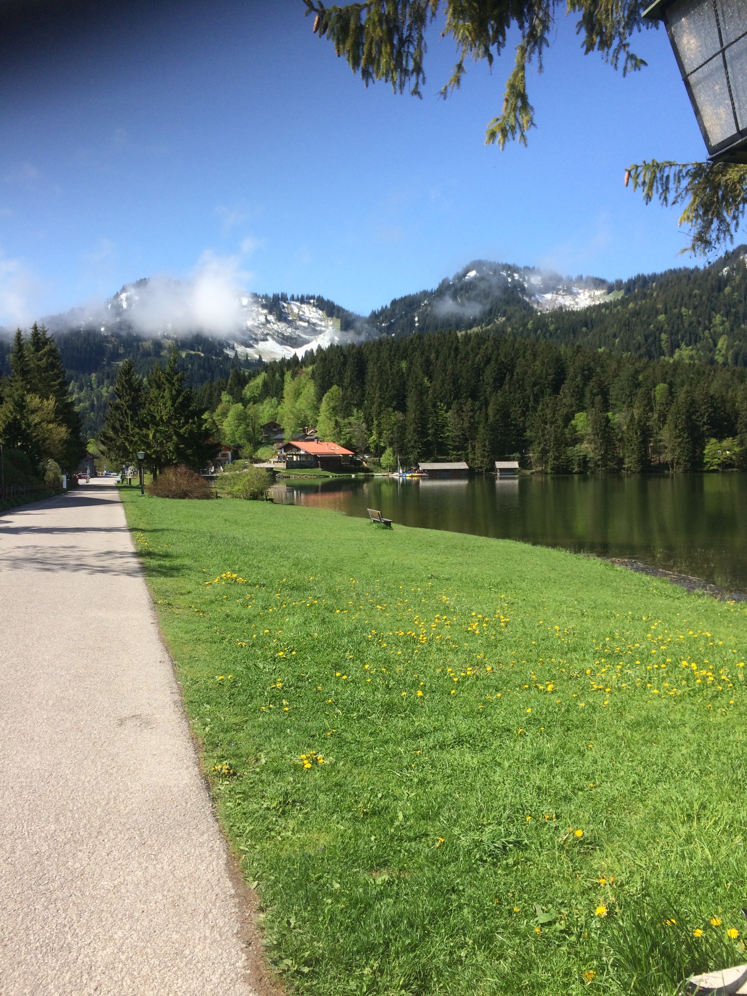
Life has been busy recently, I have been on a couple of work trips, great trip to Spitzingsee Lake in Schliersee, Germany not far from Munich for an EMEA team meeting. Great venue even if it only stopped raining on the last day.
Sunny Day
As per usual, DIY, Gardening and even the occasional trip to a car show took place and kept me out of the garage. I did snatch a few hours here and there. I had refitted the refurbished steering rack but a much longer task was running the fuel pipes over the rear suspension cage.
Rear Suspension Cage Drop
To run the fuel feed and return lines back into the spare wheel area in the boot I had to run a the fuel pipes over the rear suspension cage. This meant I had to drop the whole rear suspension cage. This is not too much of an issue as there are only eight bolts holding the four mounting bushes to the chassis and then the bolts holding on the rear trailing arms. The full suspension cage is really, really heavy so if you need to do this please take extra care. I managed to lower it without incident and ran the two pipes over the top of the cage area exiting via an existing hole in the boot. I also took the chance to change one of the small trailing arm bushes whilst it was off as well. No drama so not really worth writing up specifically. During the refitting of the cage I discovered that one of the four Metalastic mounting bushes had come apart and needed changing. As I had four new bushes on a shelf I decided to change them all. I had refitted the suspension about 3 years ago and the car has not really moved since then so it was just time based deterioration of the bush as they were all OK when I last looked at them.
Changing the bushes is not that hard, just a little awkward to get to some of the nuts inside the cage. It is however a bit of a pig getting the holes lined up when reassembling things. My recommendation is to loosely fit the bushes to the cage, offer the cage up to the chassis and only tighten the bolts once you have managed to get the bolts that go through the chassis pushed all the way through and nuts screwed on. Trying to align the bolt holes through the chassis with the bushes firmly attached to the cage is not going to work! I am speaking from experience here so don’t waste the time trying to align it with jacks, using leverage and so on.
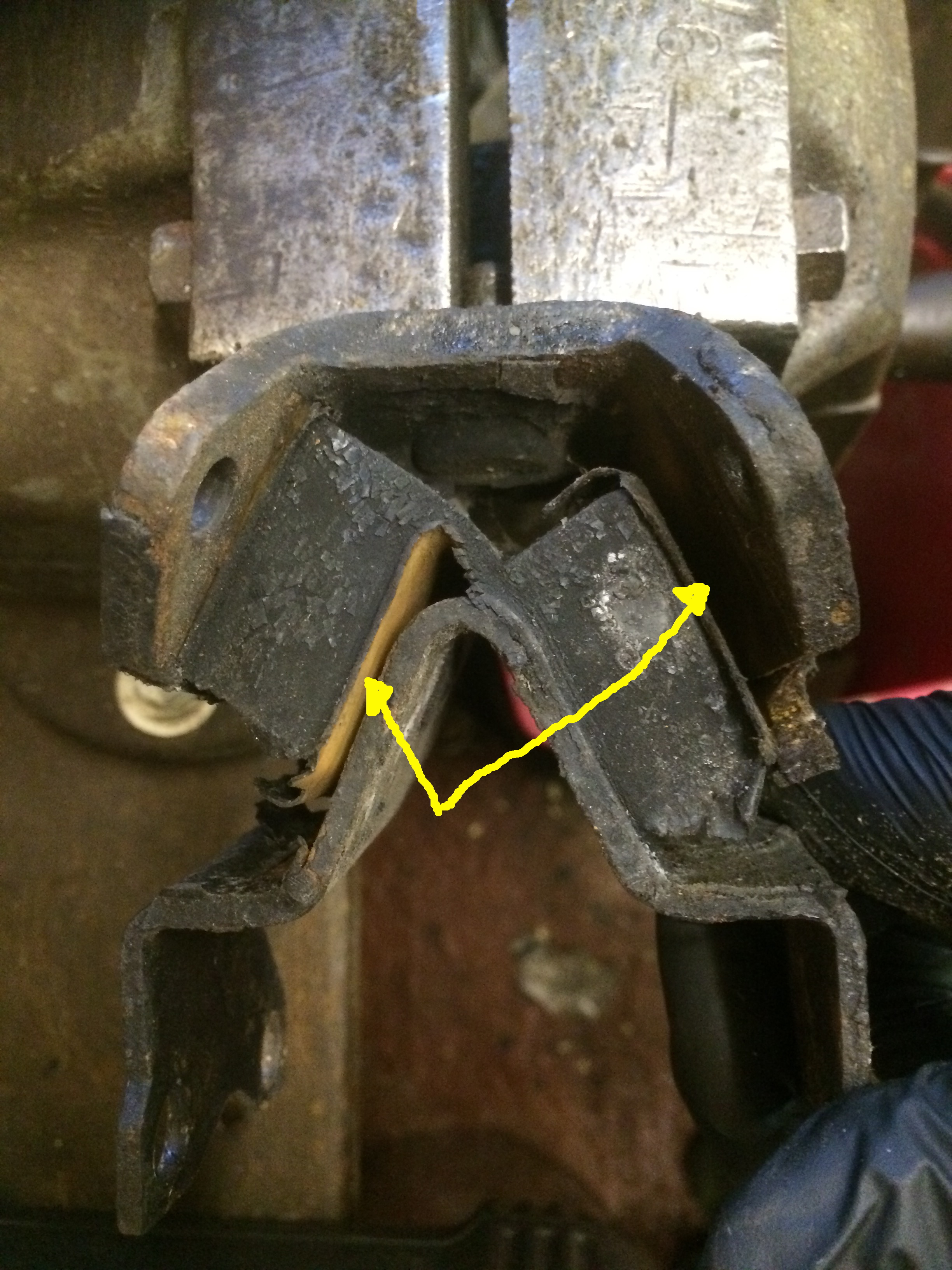
The failed bush is shown below with a little sideways pressure is applied. The faults are highlighted with the arrows. The light brown side has come away from the inverted “V” shape in the bracket. The right hand rubber has also come away from the outer bracket.
Rear Suspension Bush
Its all reassembled now and back on its wheels.
Fuel Tanks
The twin tanks in the S1,S2 and S3 models are notorious for rusting away and leaking. I did have a spare tank in the garage. It came from an old Series 3 car that I had scrapped probably 15 years ago. The fuel tank had been stashed away waiting to go into the car to replace the rusty/bodged repaired ones that are currently in the car. The S3 tanks have the low fuel drain that I will need for the single external pump option I am going to go with. Unfortunately even though I stored this tank with the view to use it, on close inspection I discovered it does have some pin holes up at the top around the fuelling hole. The pipe assembly appears to be braised in place so no chance of just welding up the holes and I don’t have the facility to braise. I will probably just put some kind of epoxy or liquid metal over the area as a temporary fix whilst I find the funds to replace both tanks with new ones. (approx £250 each)
Fitting this tank temporarily, running the outlet pipes into the boot area and searching for the switch-over valves are the next things on the TODO list.