Electronics Debugging
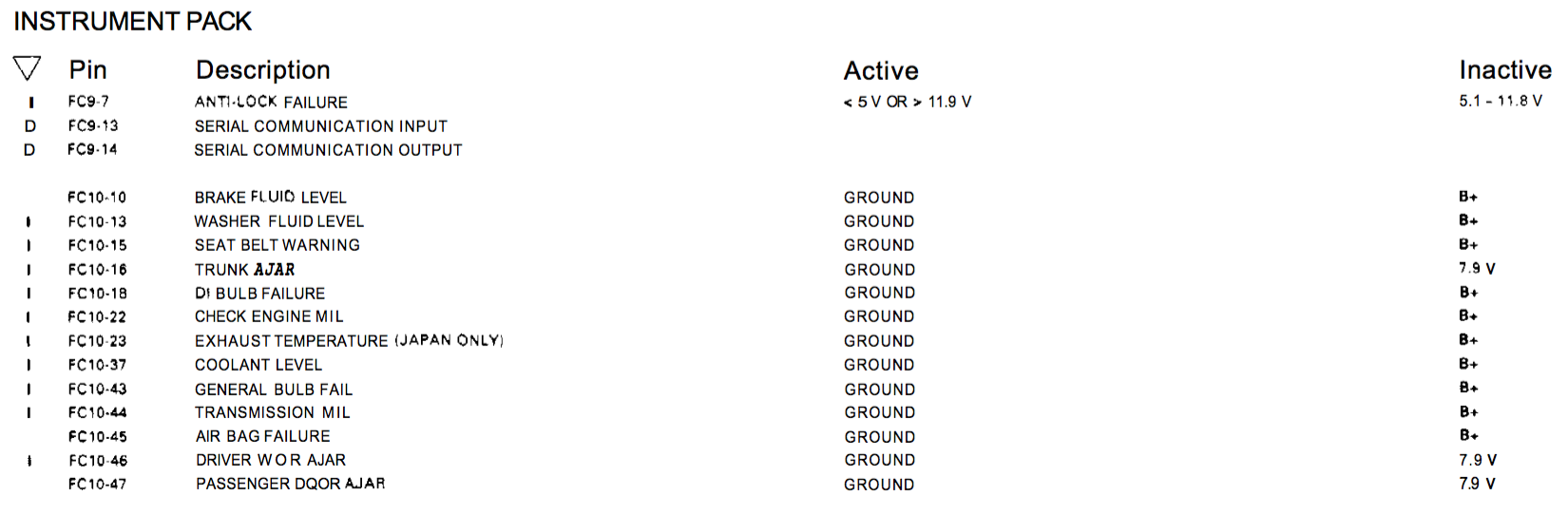
Having connected up the XJR dashboard display, I managed to get the Mileometer working showing the previous XJR milage. However it also displayed AIRBAG and FLUID repeatedly so not so good. The FLUID was straight forward to resolve by connecting the appropriate wire to ground. I misread the circuit diagram and thought the AIRBAG signal needed to be at +B. Having temporarily connected the wire to a +12V battery feed it still said AIRBAG. I tried grounding the wire, still AIRBAG! I tried adjusting the voltage to the wire using a variable resistance box but still same AIRBAG error. I took the display board out of the assembly and studied it closely.
I traced the input wire (pin 45) to an input on a surface mounted integrated chip with HC151 printed upon it. This is an 8:1 multiplexer chip. My guess is that the inputs are sequentially scanned and the outputs read to determine the status of the input signals. What that means is that if the chip is faulty (possibly damaged by me directly connecting 12V to the input?) then I cant just tie the outputs to one state as I will get other errors flagged as well. I am not sure this is the problem because the detail in the circuit diagram does say it is either ground or +B. The input circuit seems to have the signal going to the middle of a pair of resistors so the input voltage would be split in half anyway. The spec of the chip states 6V maximum input which is a little close, especially as my old XJS with an AJ16 engine used to run at 13.8V most of the time!
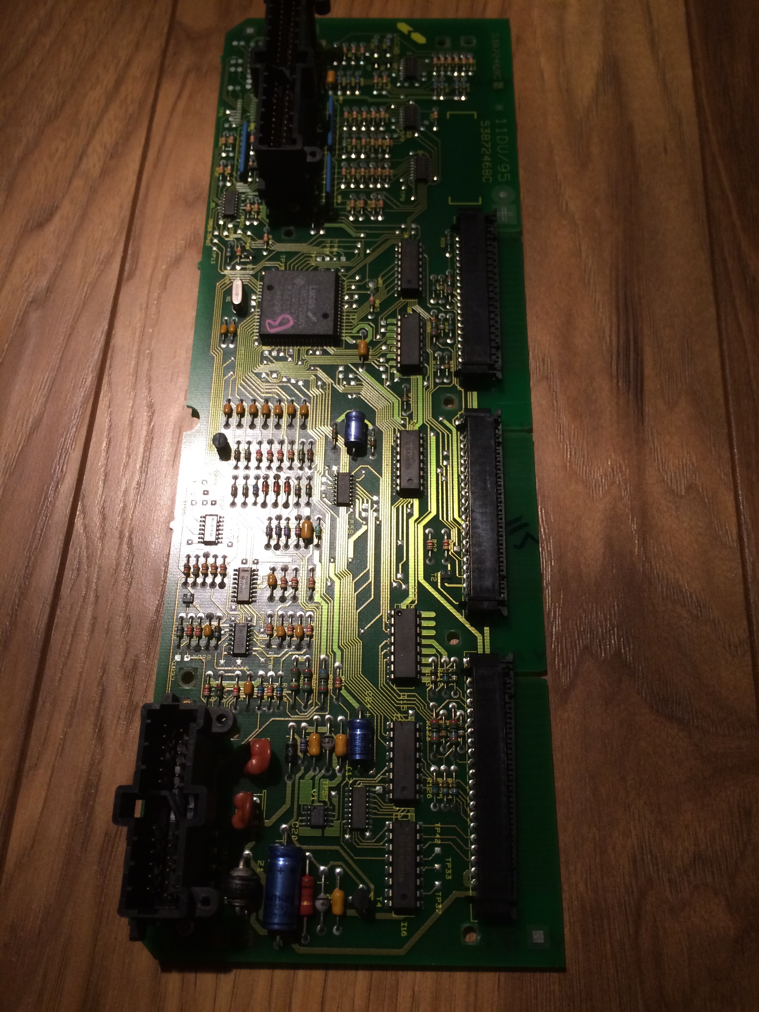
I have ordered a replacement IC (or 5) just in case. They are not expensive but I will have to wait a few days for them to arrive. The suspect chip (11) is highlighted by the red arrow in the picture below.

The image below shows the location of the input signal, the +B and the ground points and the signal feed to pin 12 of IC 11

2 Responses