I have manage to get a ticket to the Strata Hadoop Conference this week. It looks like it is going to be very interesting. I have a gold ticket which allows access to the training sessions on Tuesday so that’s my first day. I also have to help out on the company stand on Wednesday and Thursday but I am sure I will attend at least some of the keynotes.
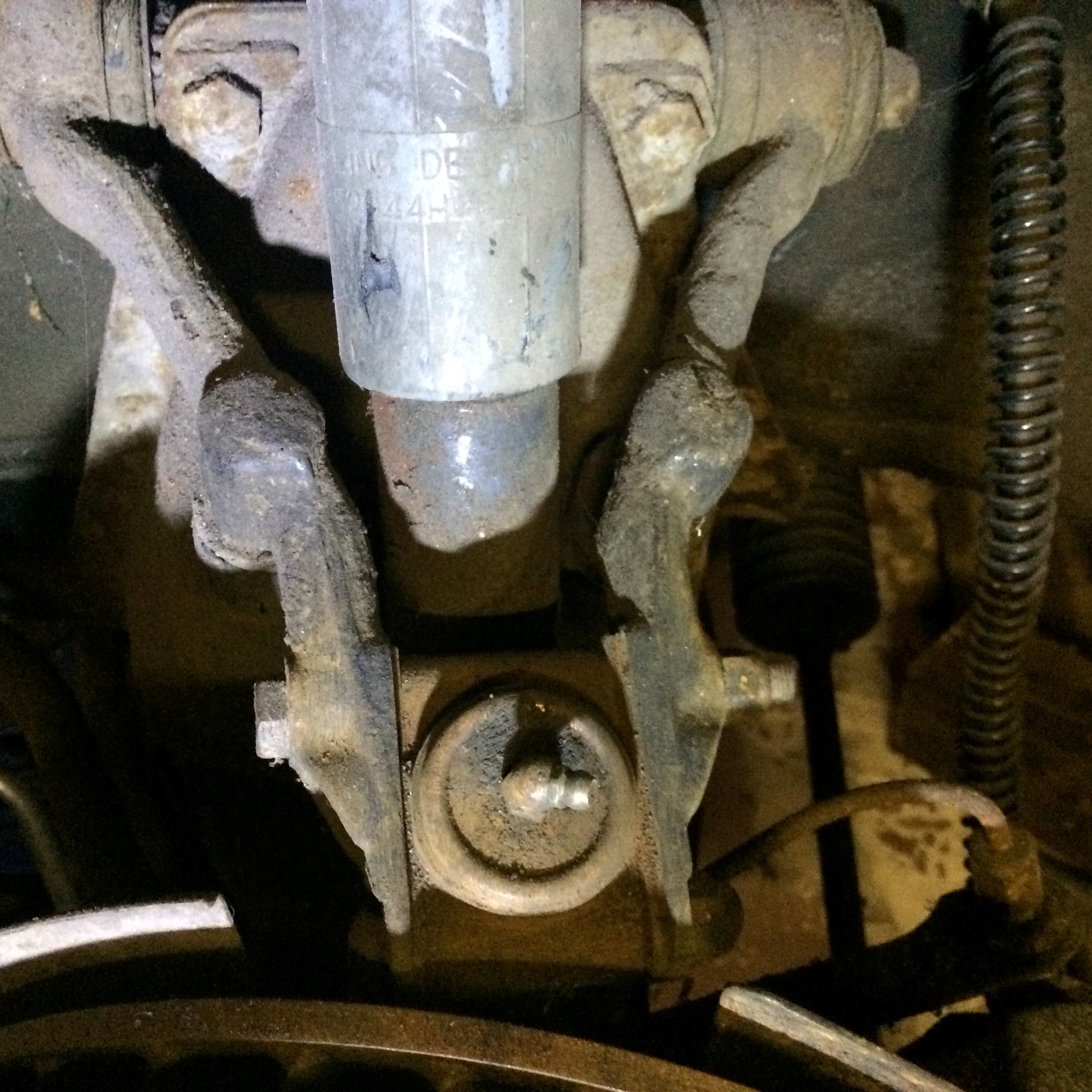
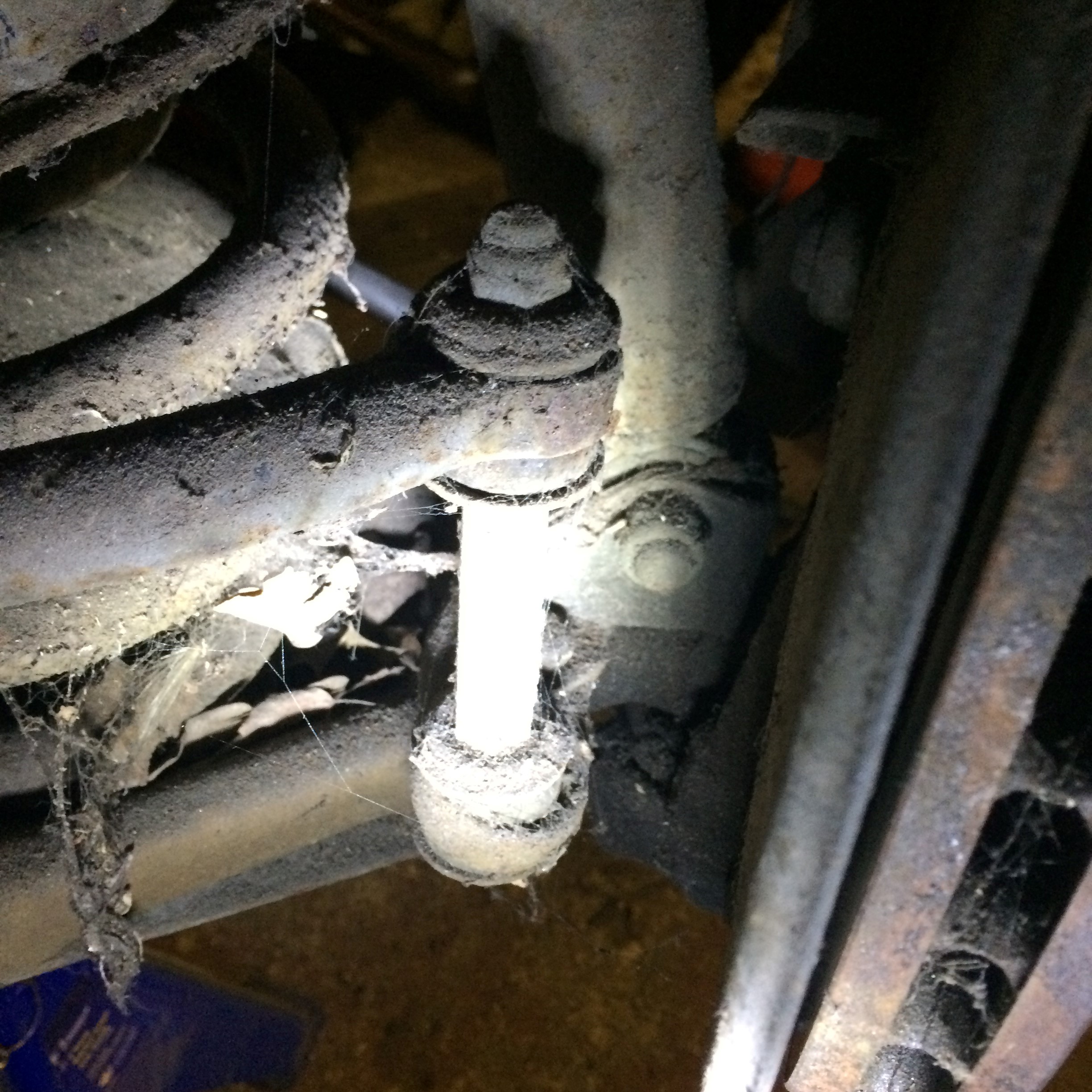
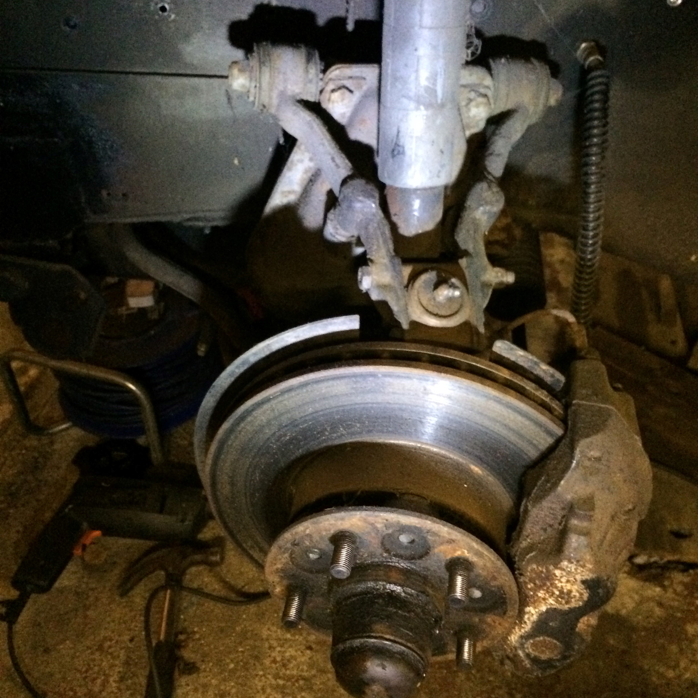
The front suspension had not been touched in years. The track rod ends although were probably OK wear wise but looked bad because the rubber “boots” were perished. The “boots” on the lower ball joints looked bad too. Springs, shock absorbers and all the bushes looked rusty and worse for wear.
I therefore decide to replace all rubber bushes and ball joints and clean up as I went along. First thing was to order all the associated parts from a few suppliers attempting to get the best price and availability. I had already changed the front subframe bushes with poly bushes however I went with standard rubber for the rest.
Of course I could not resist cleaning and painting along the way and so it took a lot longer than I thought it would. I have still one side to reassemble but the drivers side is now complete. It looks reasonably good even if I say so myself. during this rebuild, I am not after concourse or any thing close to it. I just want it to not look rusty and work the way it should.
There were a few minor “challenges” along the way. Please be very careful removing the springs as with even all the weight of the car on one spring it still has a lot of tension forcing the spring tray downwards. I did not have the correct spring compressor so I used a jack, a number of G cramps and a threaded rod to remove and re-assemble the springs. Some of that pressure did damage the threads so I had to replace some bolts. I did clean up and repaint the springs and the surrounding metal work too. The spring trays were full of rust and road debris. It took a lot of cleaning away of the debris before I could even separate the springs from the tray. The lower fulcrum shaft on the drivers side was a bit of a pain to remove. Unfortunately I did damage the thread a little in my efforts to remove it. Luckily re-cutting/cleaning up the thread with a die managed to save it. It was not the cost of the replacement of the shaft that was the issue but more of the fact it had a 4-5 week lead time. (I have since seen some in stock! and half the price)
Post Re-Conditioning
Here are a few photos of the state of the suspension before I started
Top of spring assembly – a little rusty and you can see the perished rubber on the bump stop.Top of Suspension – Rusty and worn Shock Absorber. Remember to clean up around the upper ball joint and take note of the number of spacer used so you can put them back in correctlyAnti-Roll Bar BushesTop wishbone bush – not too bad looking. There was a fair amount of wear internally thoughPassenger side suspension
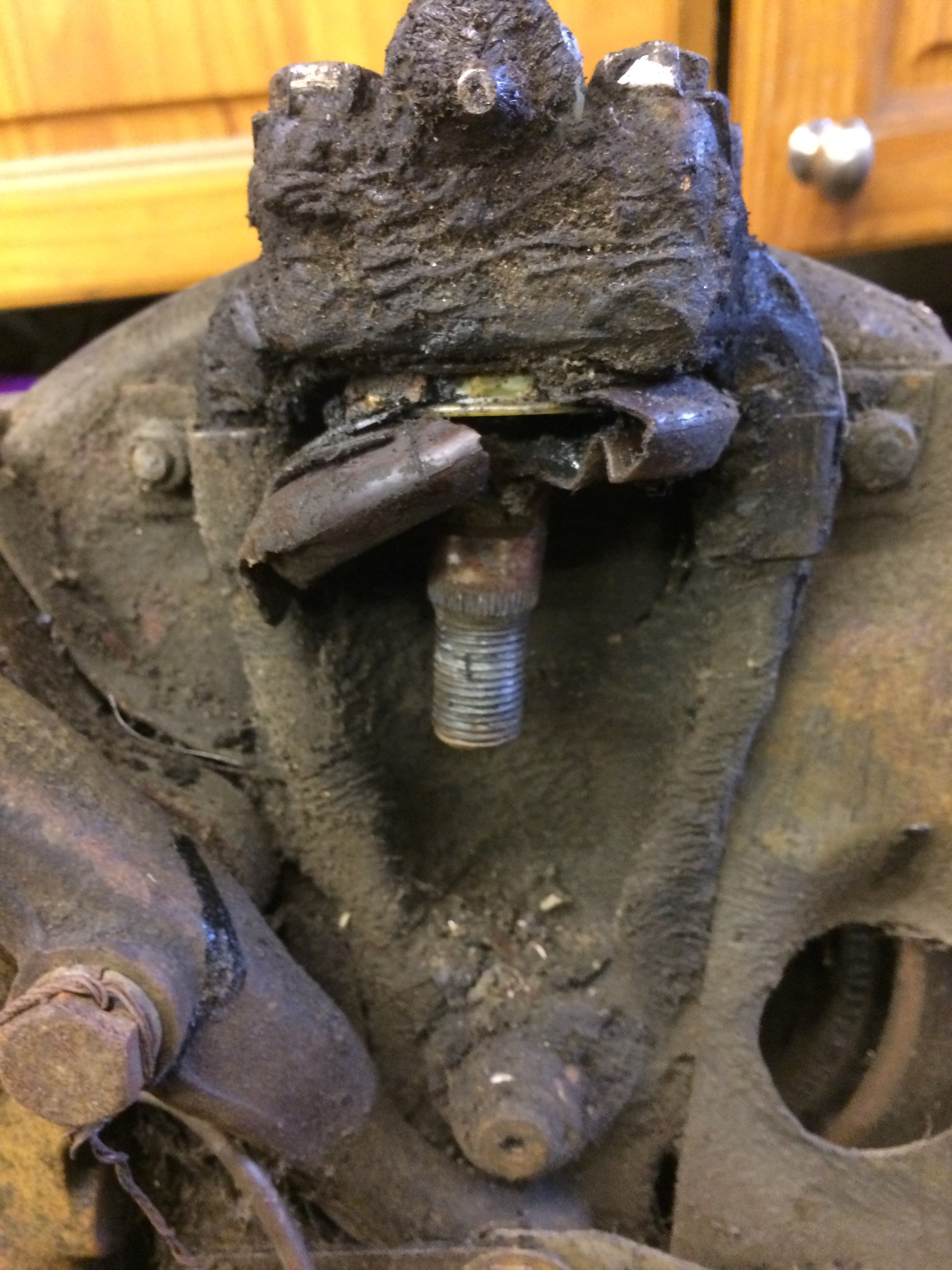
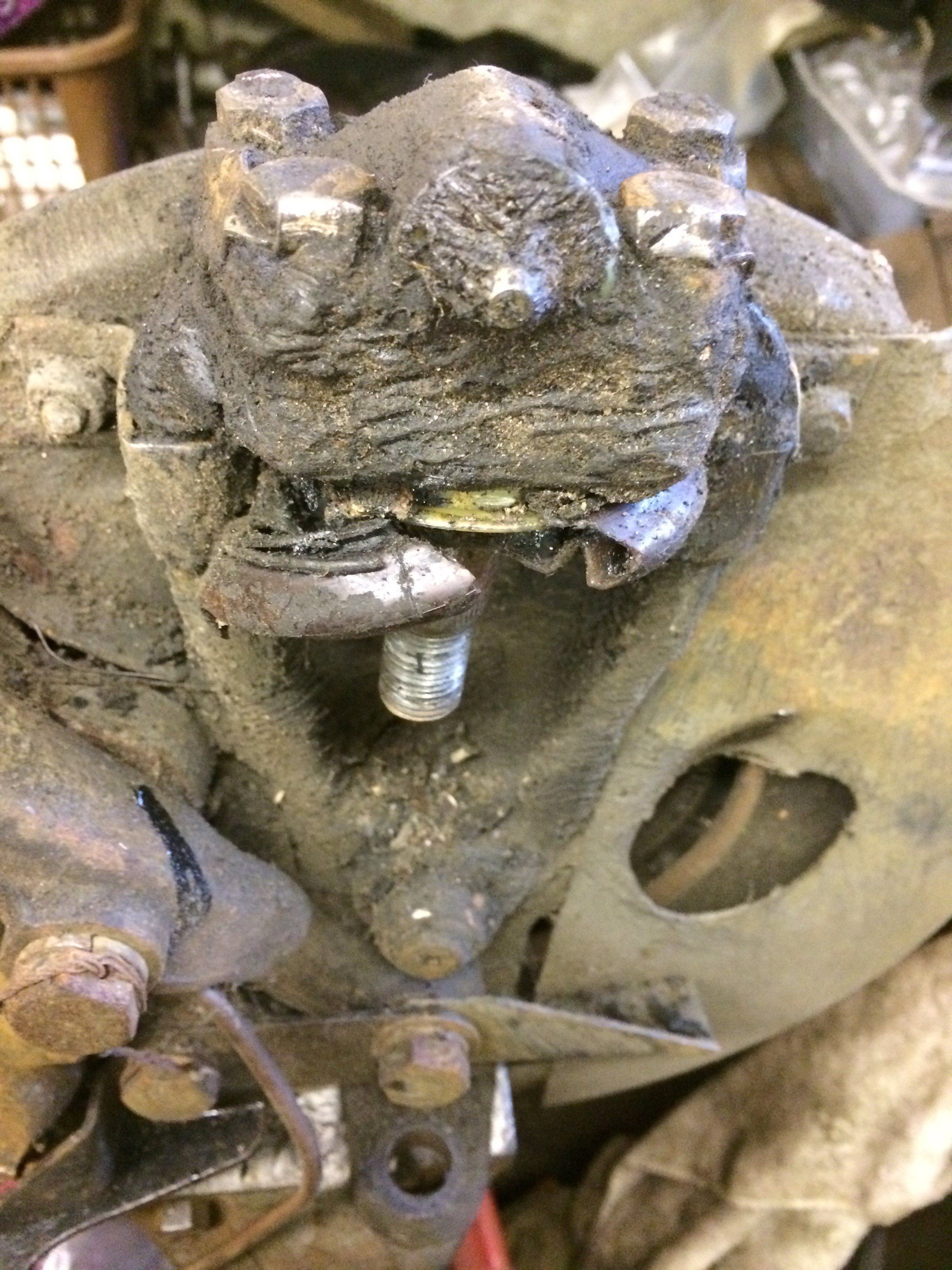
Lower ball joint replacement
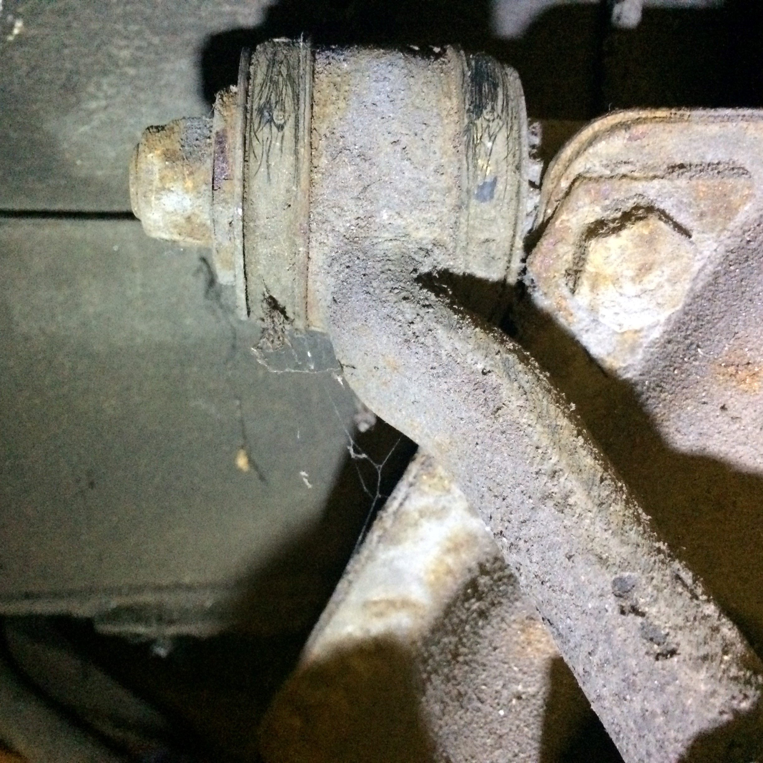
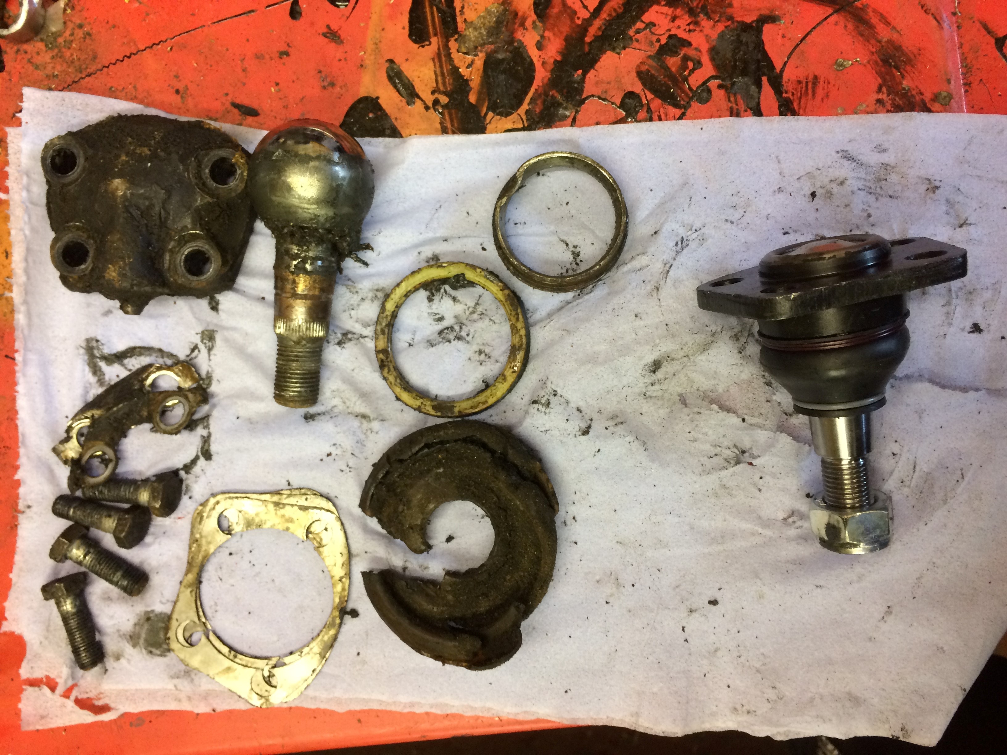
As from the first pictures in this post, you can see the split ball joint covers, if nothing else needed replacing. Removal of the lower ball joint was pretty straight forward and resulted in the items pictured below along with the more modern, single piece replacement on the right hand side. You do have to remove the metal ring insert prior to fitting the new style ball joint.
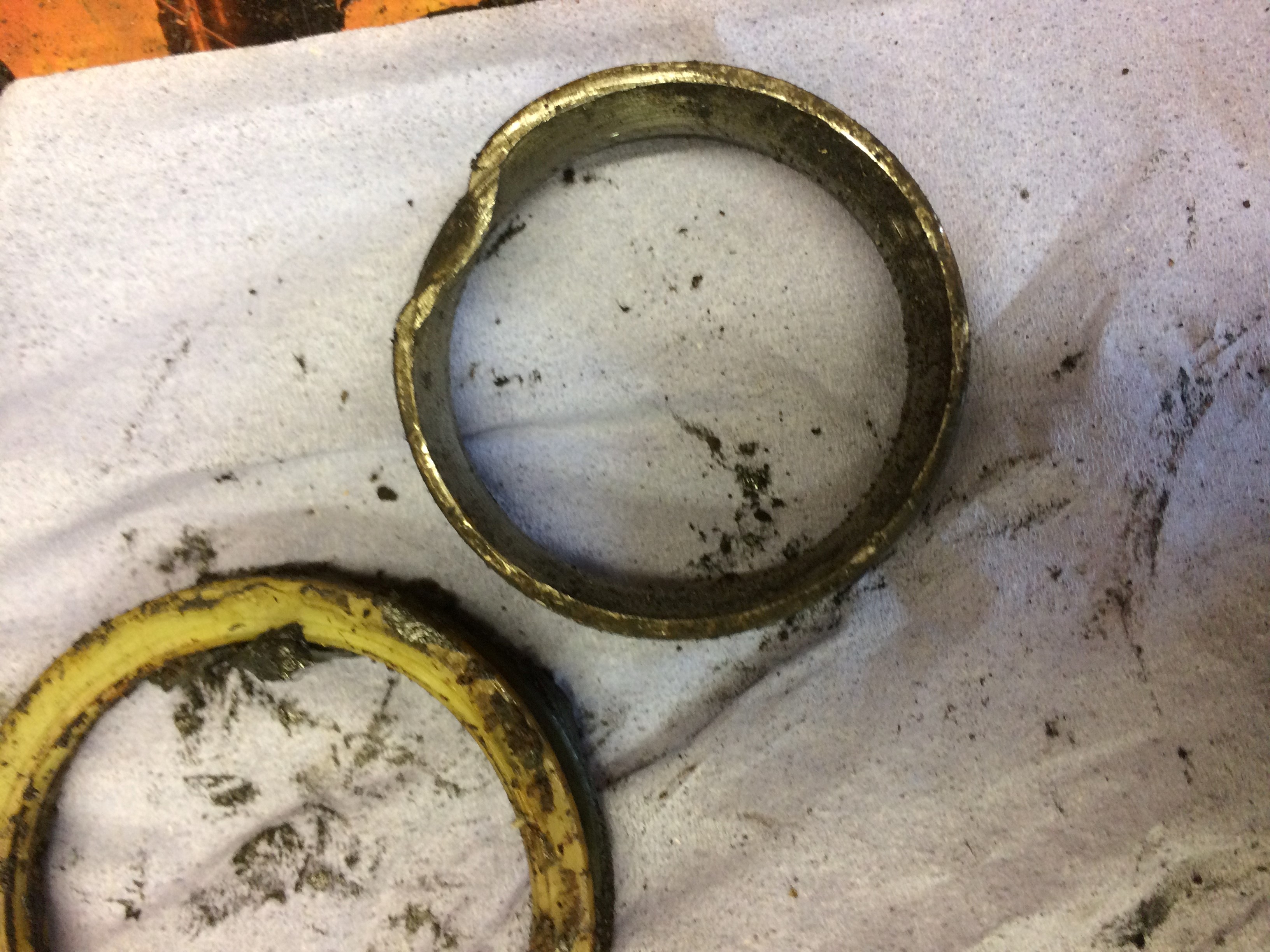
Lower Ball Joint DisassembledThere was some damage caused to the metal ring during removal in this image. This is the ring that needs to be removed to make way for the replacement ball joint. It will not be used again.Top Ball joint goes in here with insert removed. The ring insert needs to be pushed out downwards/outwards
The only non standard thing I did was to not insert all of the spacer rings at the top of the springs. The XJR engine is an Aluminium block rather than the cast block of the original XJ6 engine. It seemed to make sense that the front of the car would therefore sit a little higher with a lighter engine installed. With that in mind I left out the two, quarter inch thick nylon/plastic ring spacers back on the top of the springs. I might come to regret that decision so we will have to wait and see.
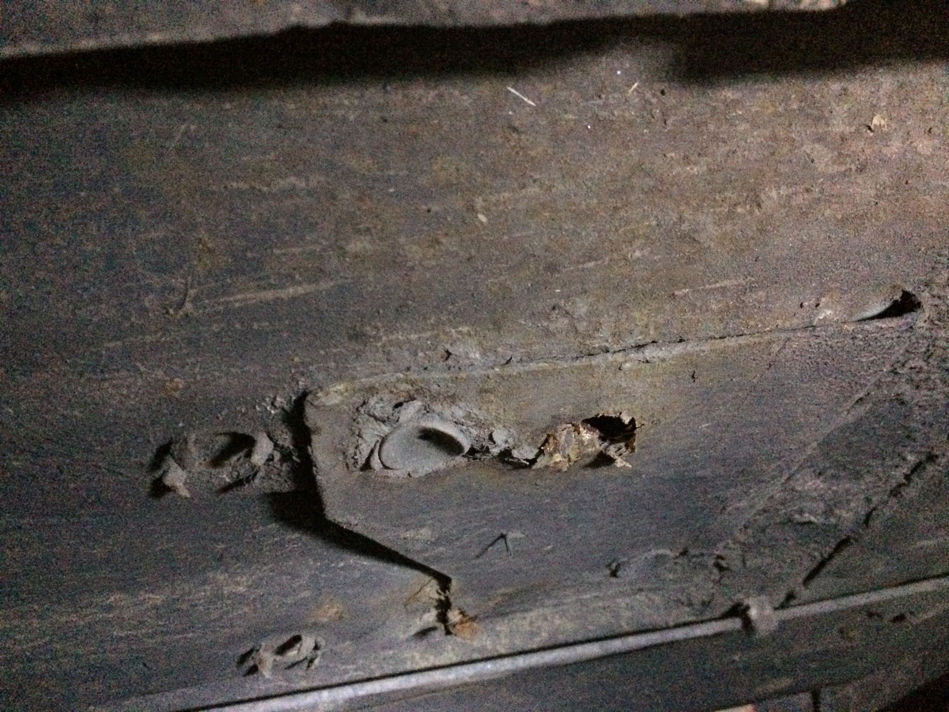
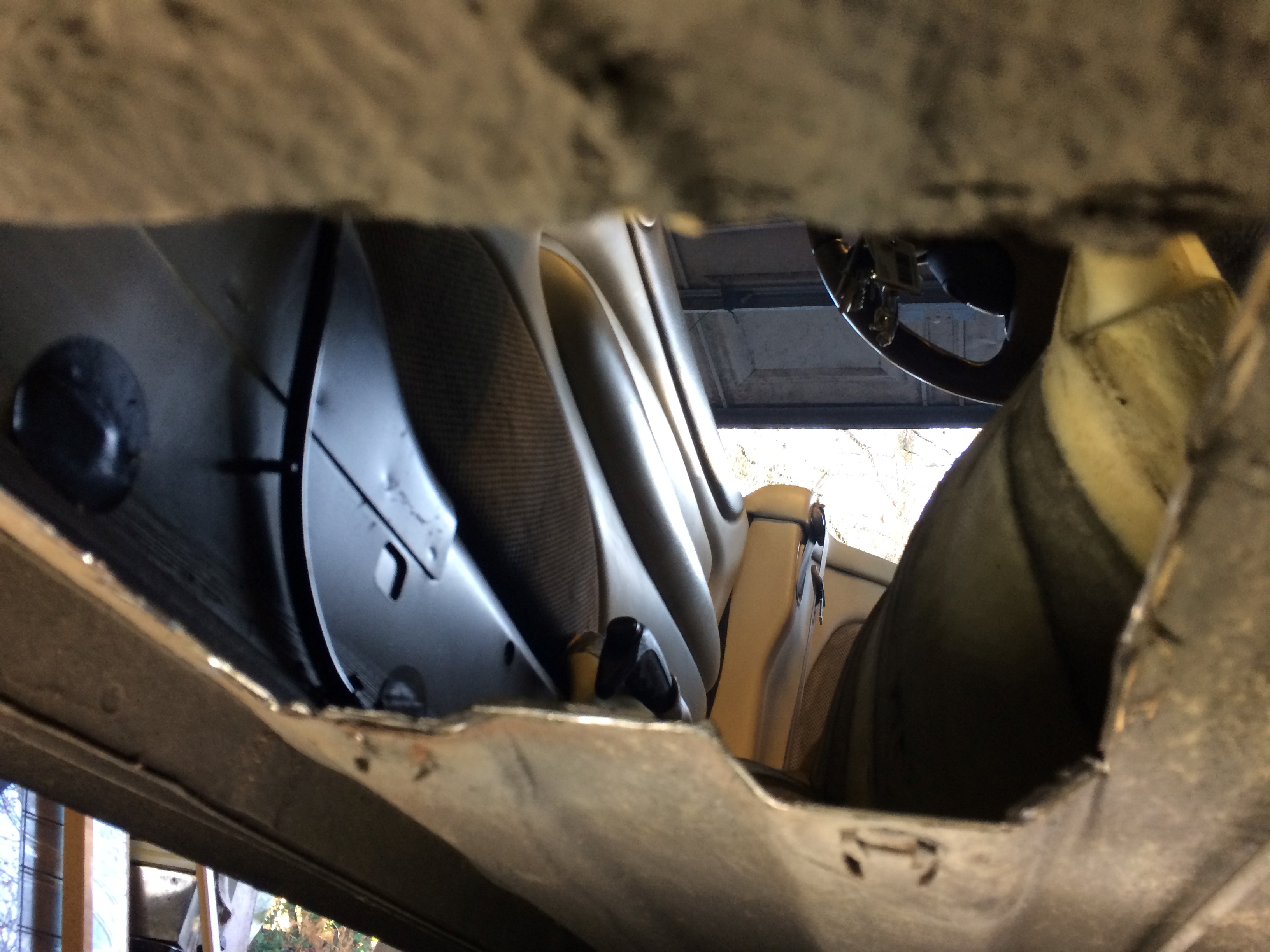
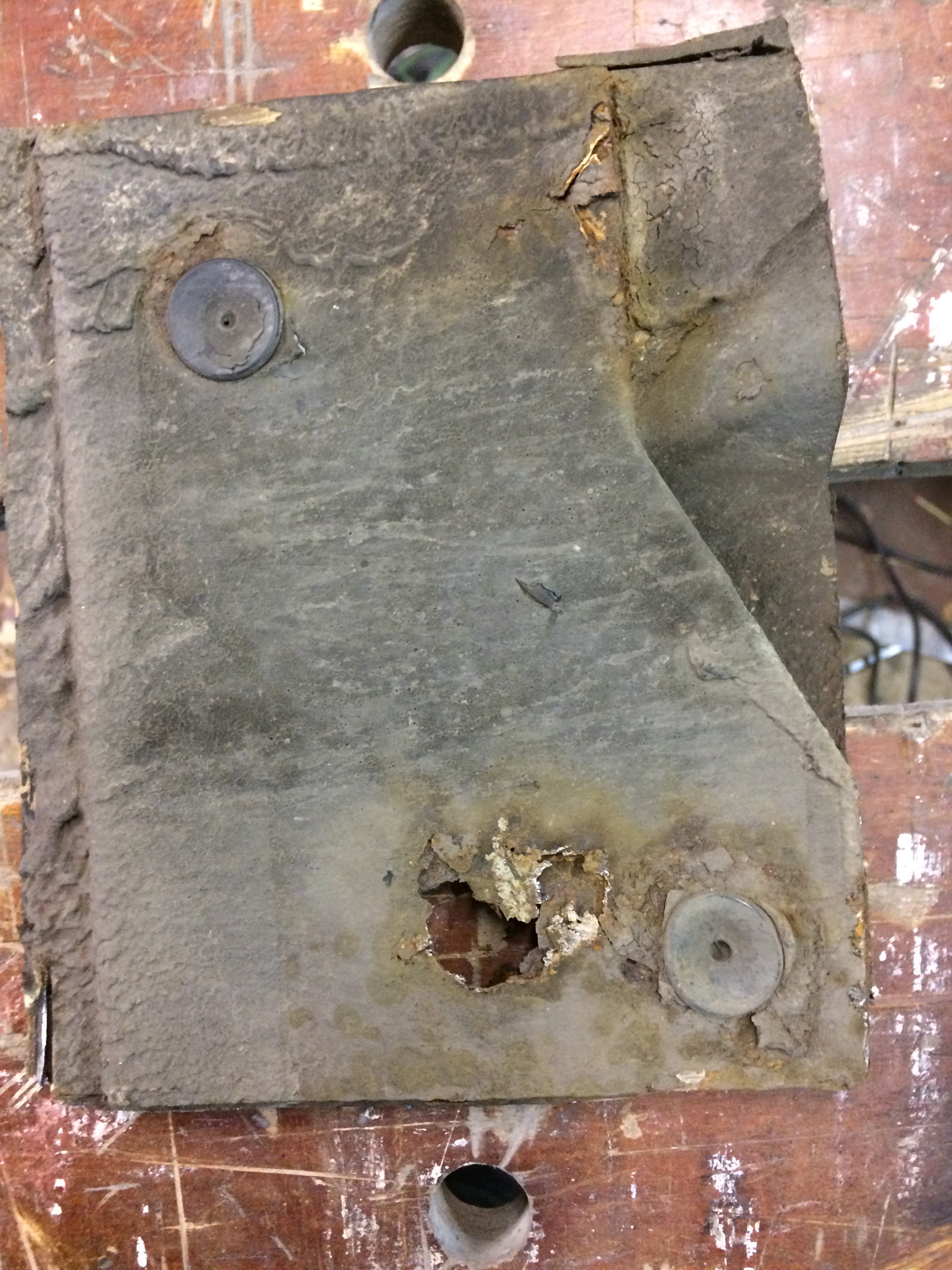
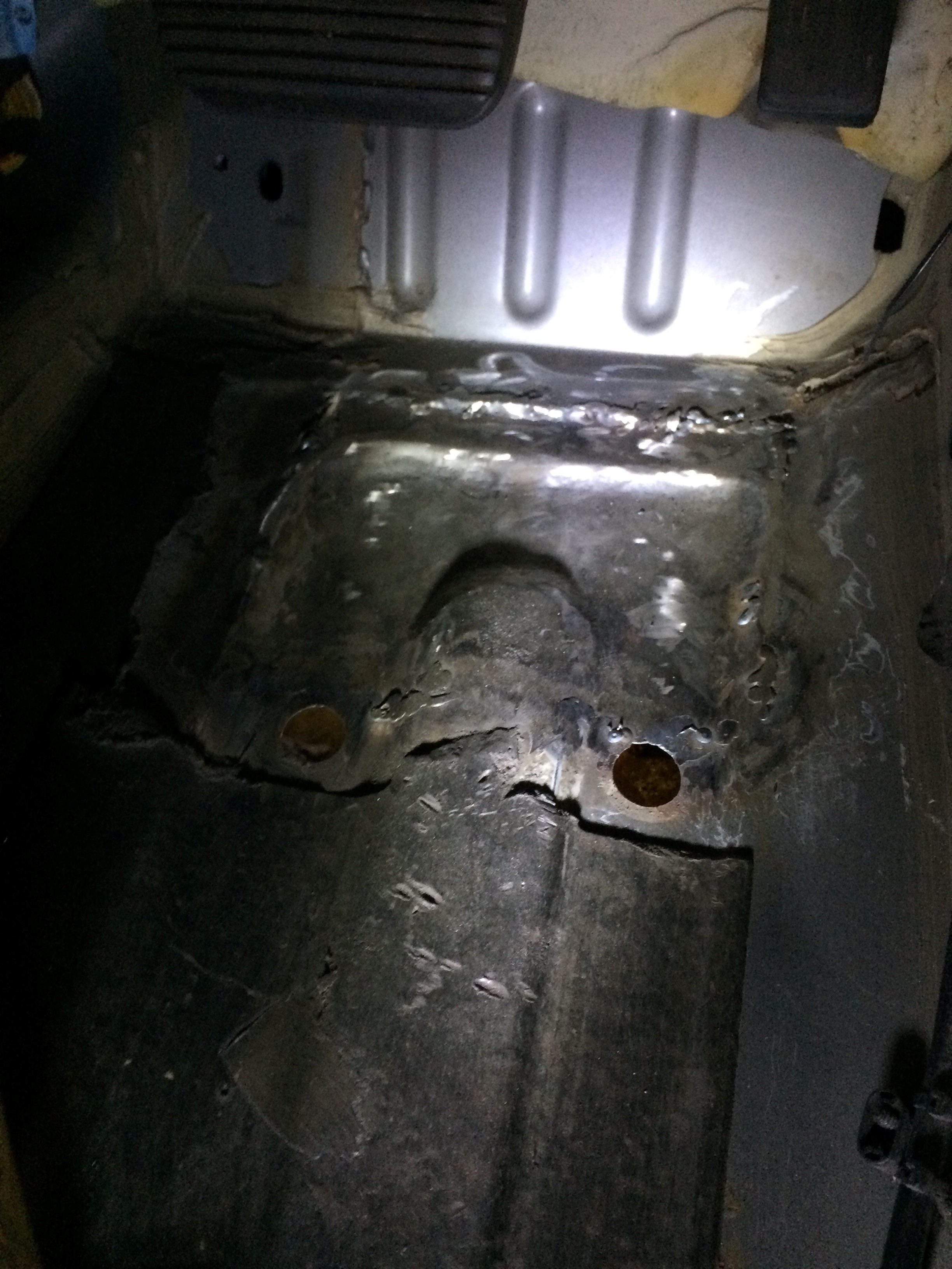
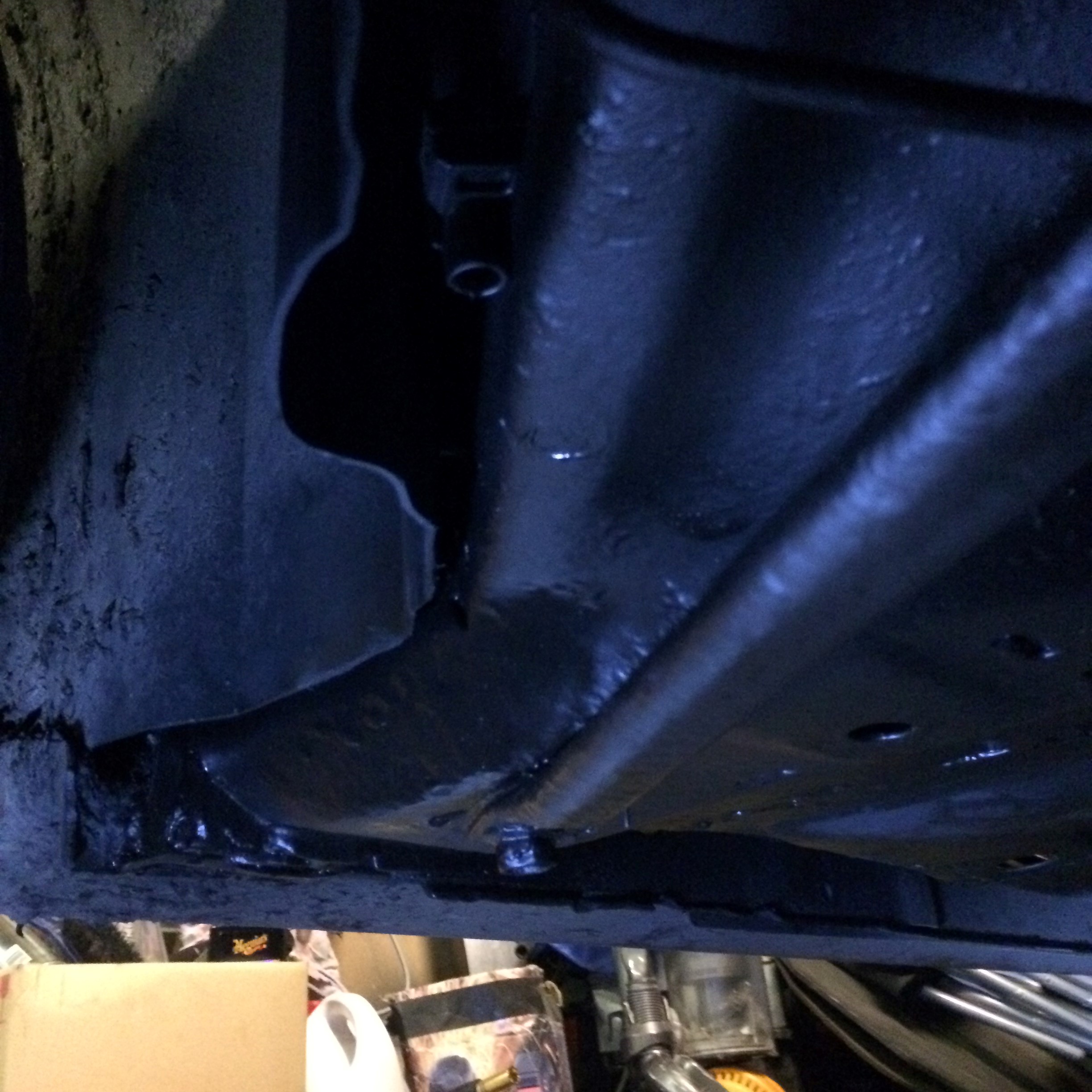
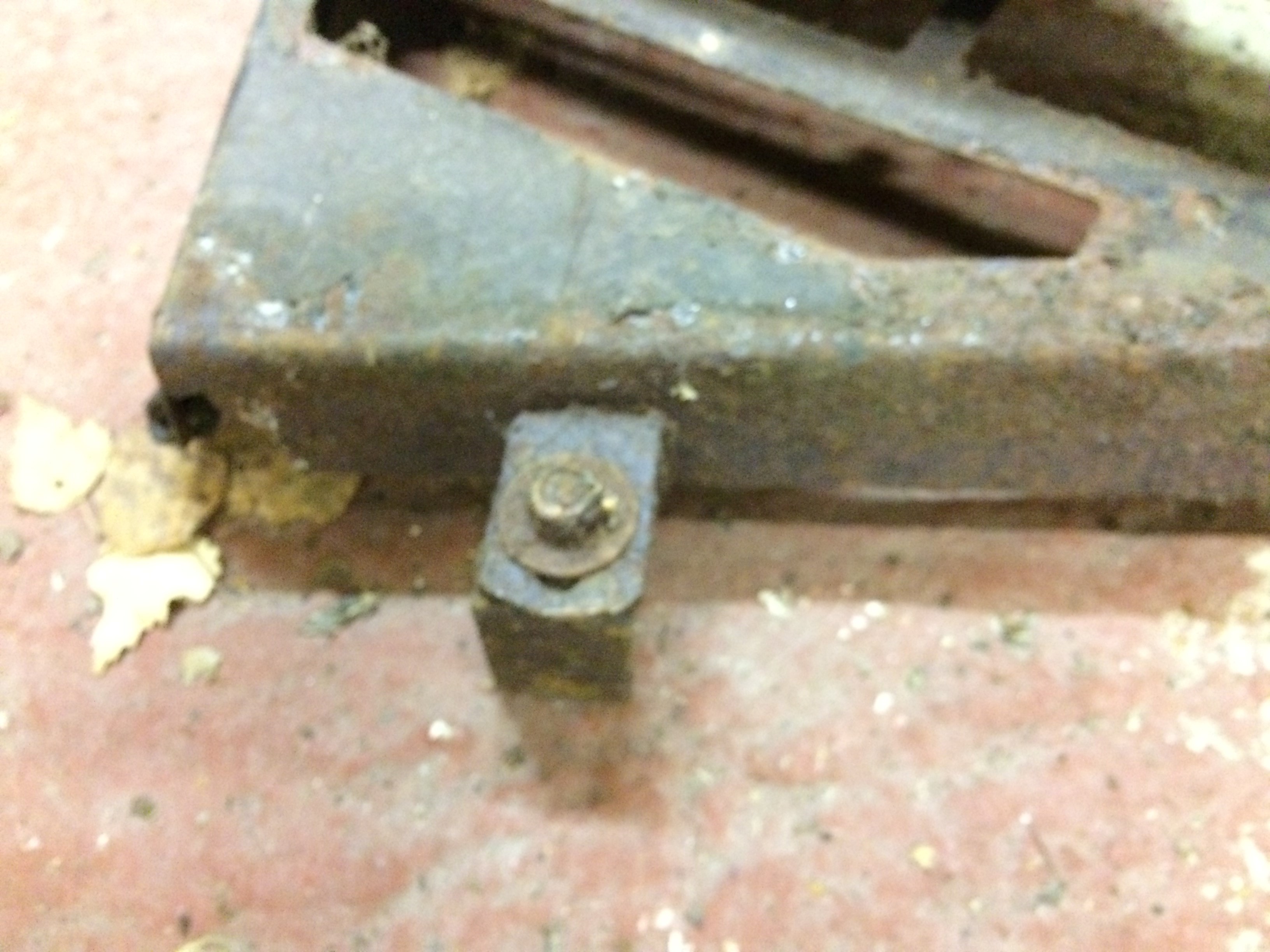
As per my old XJS, the XKR has a similar floor pan with a small metal plate welded onto the underside of the floor. It is around about where the drivers feet go. This added panel is flat whereas the floor pan has stepped channels (don’t know how else to describe it) to give some more rigidity to the panel. This leaves gaps between to two panels where water can collect and then causes rust to eat through the floor.
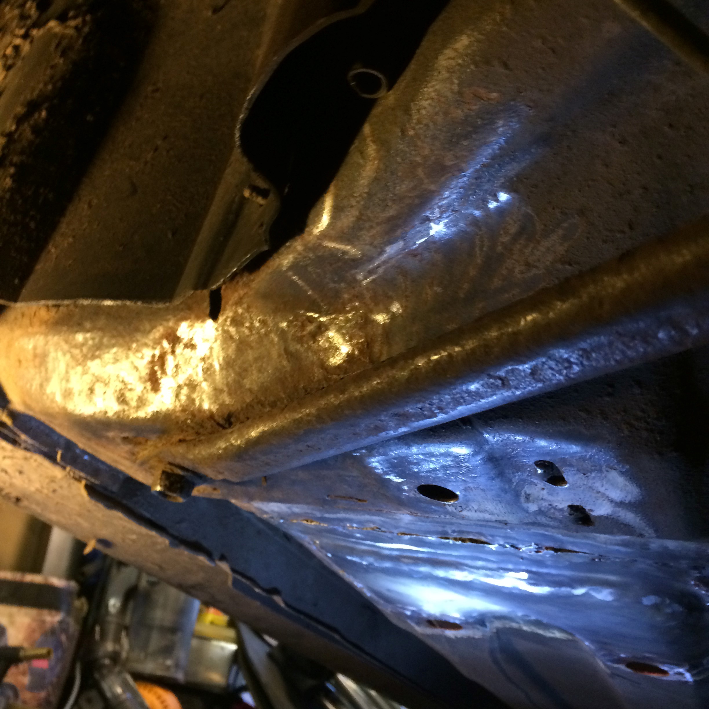
Underside hole & flat panel. You can see the gap between the panels on the left hand side.Inside view of rotten panel
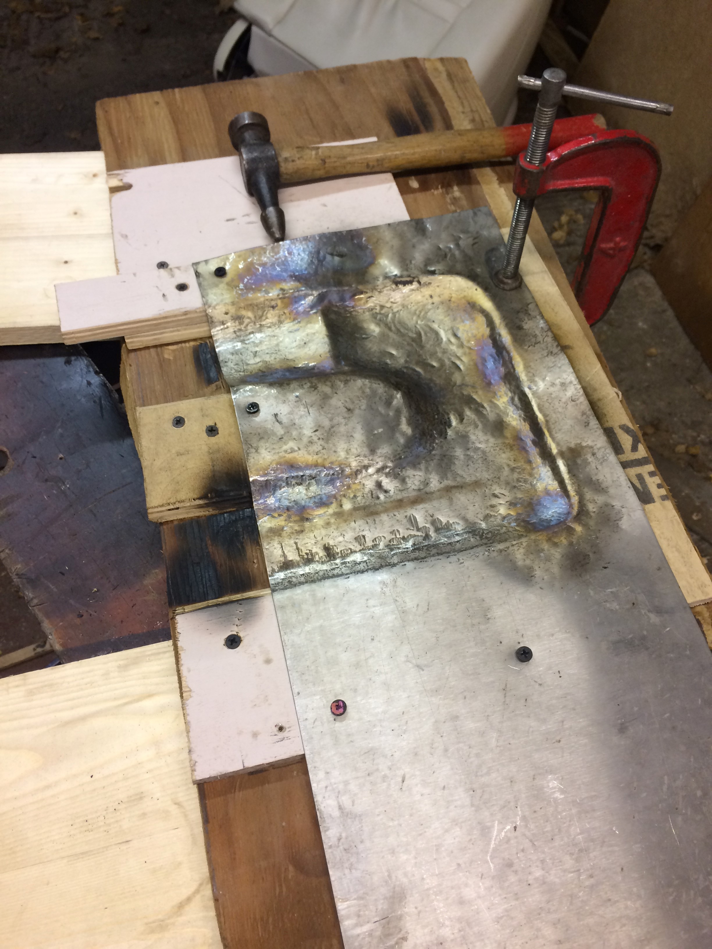
The rust in the drivers side floor was discovered during the 100k service. The passengers side had been repaired previously as part of the pre-delivery service/MOT when I purchased the car. Just over two years later, the drivers side will now cause an MOT failure too. Repair panels are available for £100 (when VAT and delivery are included). There is some shape to the panel, it is not just flat, (The underside panel is). Under the car there is loads of under-seal which hides the repair and of course there is the carpet on the top side. I therefore made up a repair panel to fit. I could just put in a flat panel but I made a jig to fabricate something that looks more like the original interior view.
Carpet removal
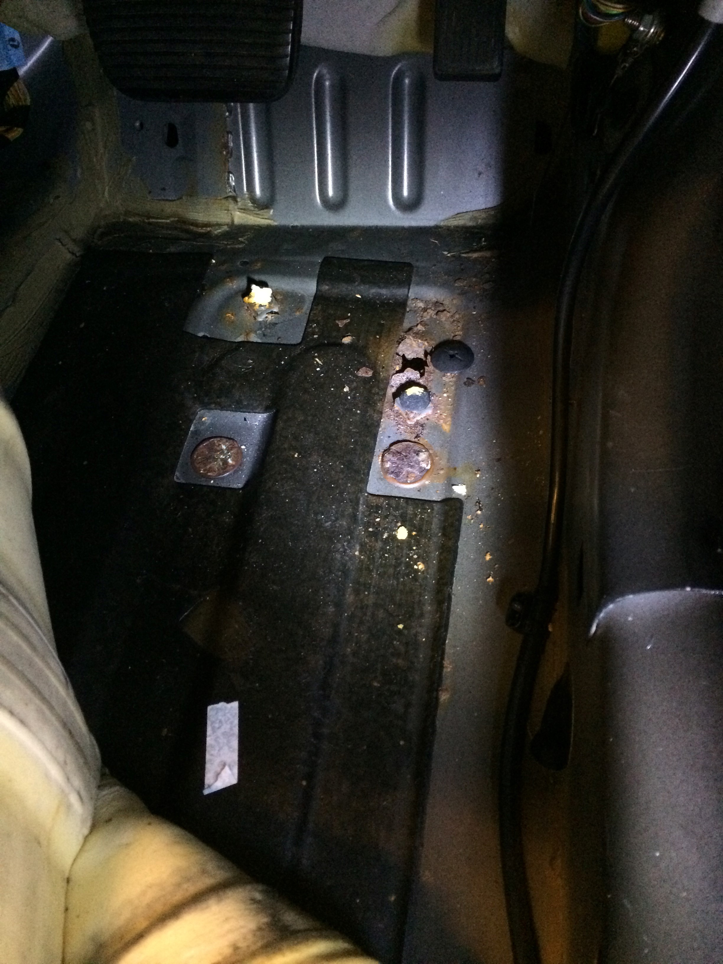
The first challenge is to get to the panel by removing the carpet out of the way. You have to remove the tread plate which is held in by three bolts that are under the decal plate. The decal can be removed by applying heat and carefully prying it off. You can use old credit/loyalty cards to slide under the decal, applying heat as you go along. The decal was removed successfully without damaging it. It is only glued on, so I will use some double sided tape to fix it back in place.
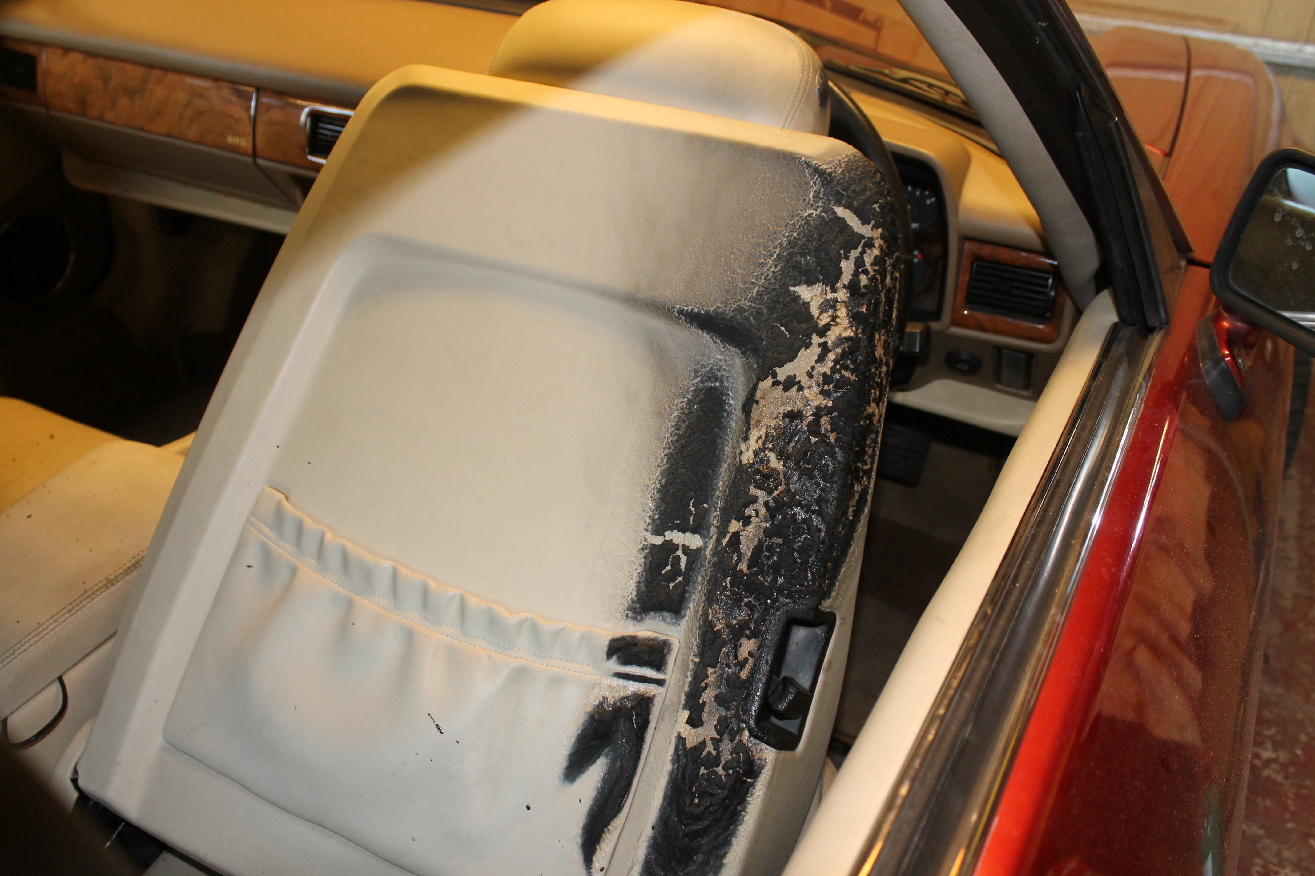
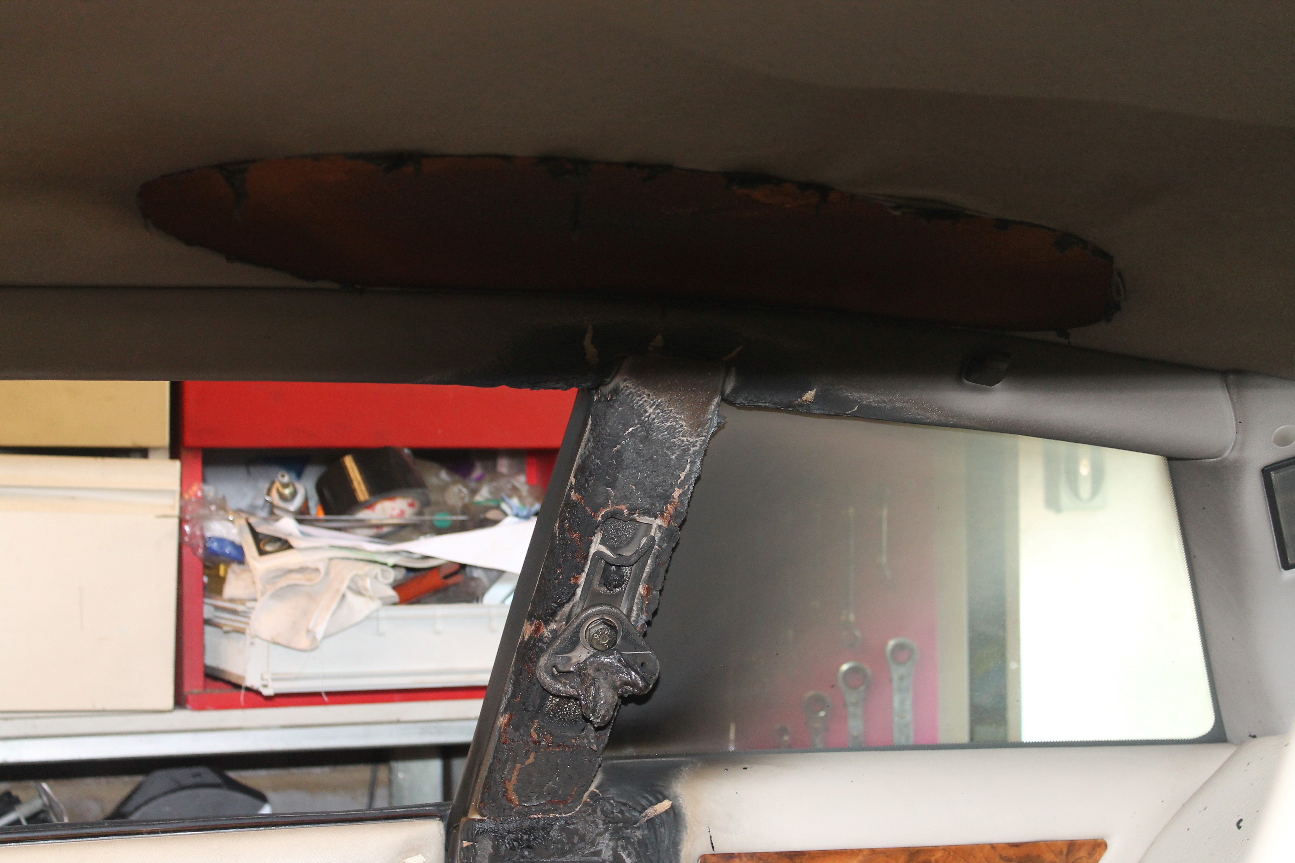
Keeping the carpet out of the way is a major priority of mine! That is how I set light to my XJS interior! I was welding in a plate around the seat belt mounting point from under the car. The carpet fell back onto the welding area. The carpet caught light first. That set light to the seat belt, which burned up the B post and seat back, finally burning the headliner. This damage wrote off the car. A sad end to my 9 years of ownership.
Burnt Carpet and post areaBurnt SeatB post, seat belt and head liner damage
Obviously I do not want history to repeat itself!
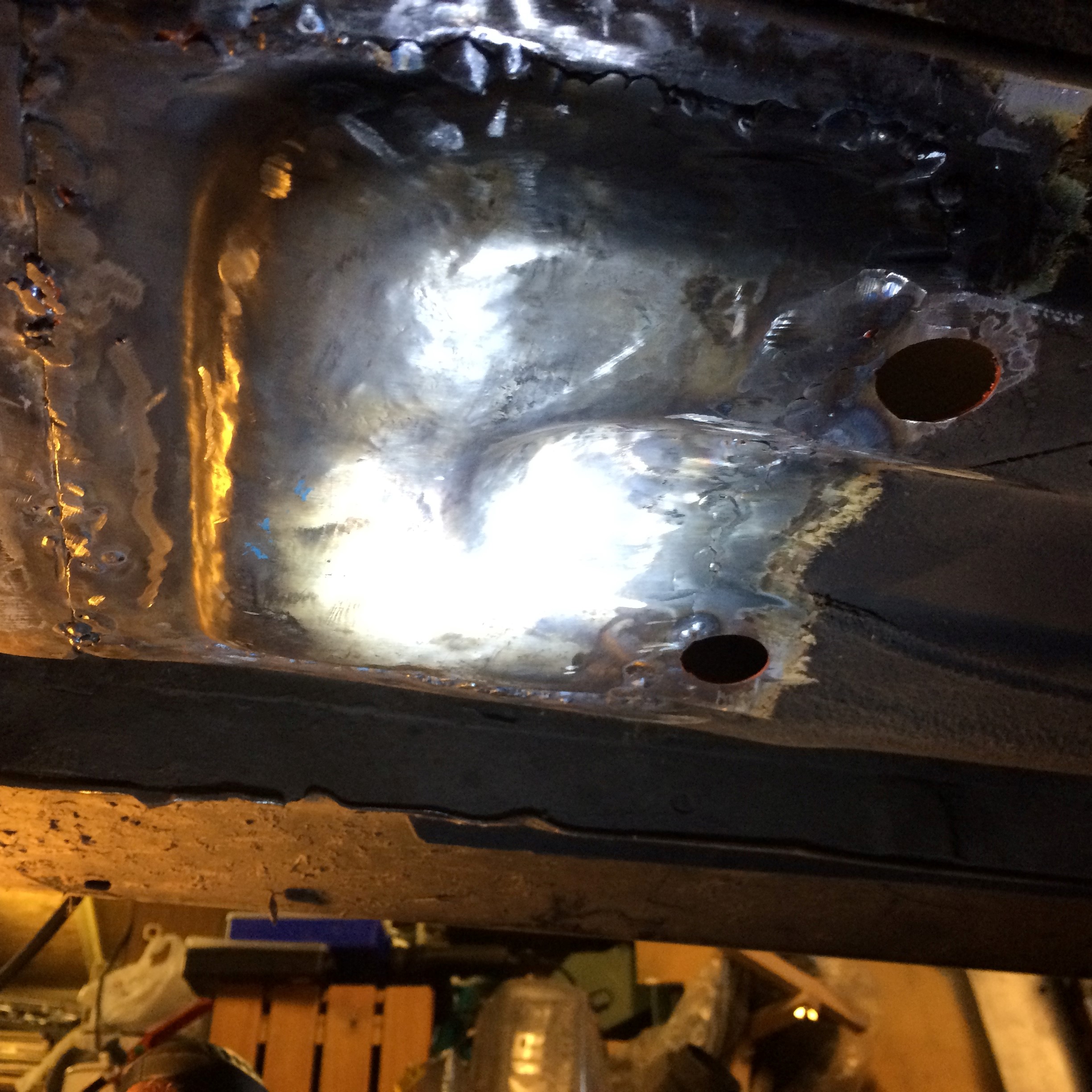
You can see the progress of the repair in the images below:
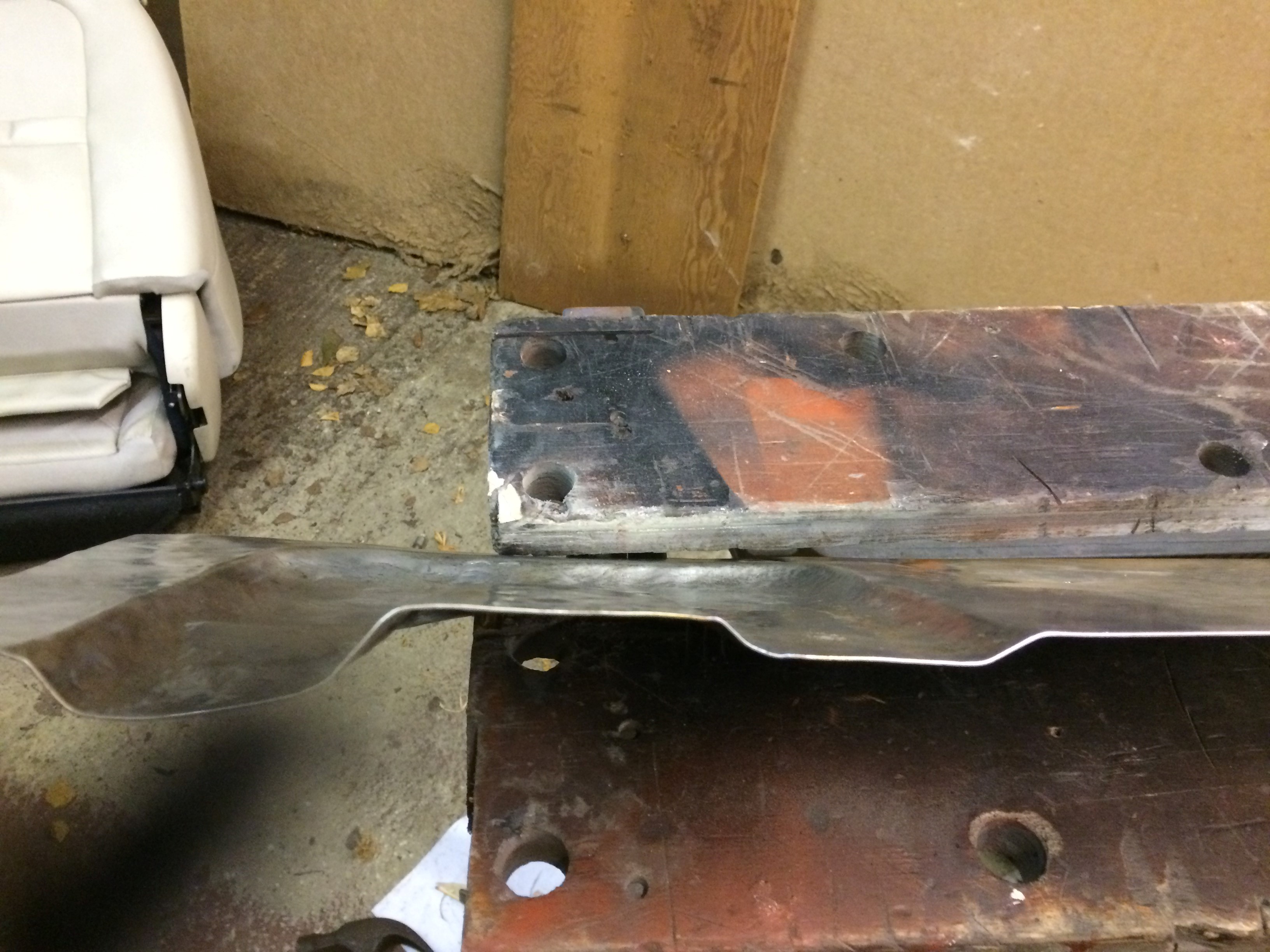
Hole cut out – looking from the insideRough cut hole – looking up close from underneath. Notice the difference in depth of the two channels.This is the was removed metal – view of the undersideCut out piece – this was the insidePanel in Jig 1Closer view of the panel in the jigEnd on view of repair panel showing the difference in depth of the two “gulleys”
Fitting the panel took a bit of work as there is very limited space in the foot-well especially as I did not totally remove the carpet. I also used my brothers MIG welder with an gas feed rather than the no-gas wire welder I am used too. It took a lot of trial and effort plus a significant amount of grinding to get a reasonable looking result.
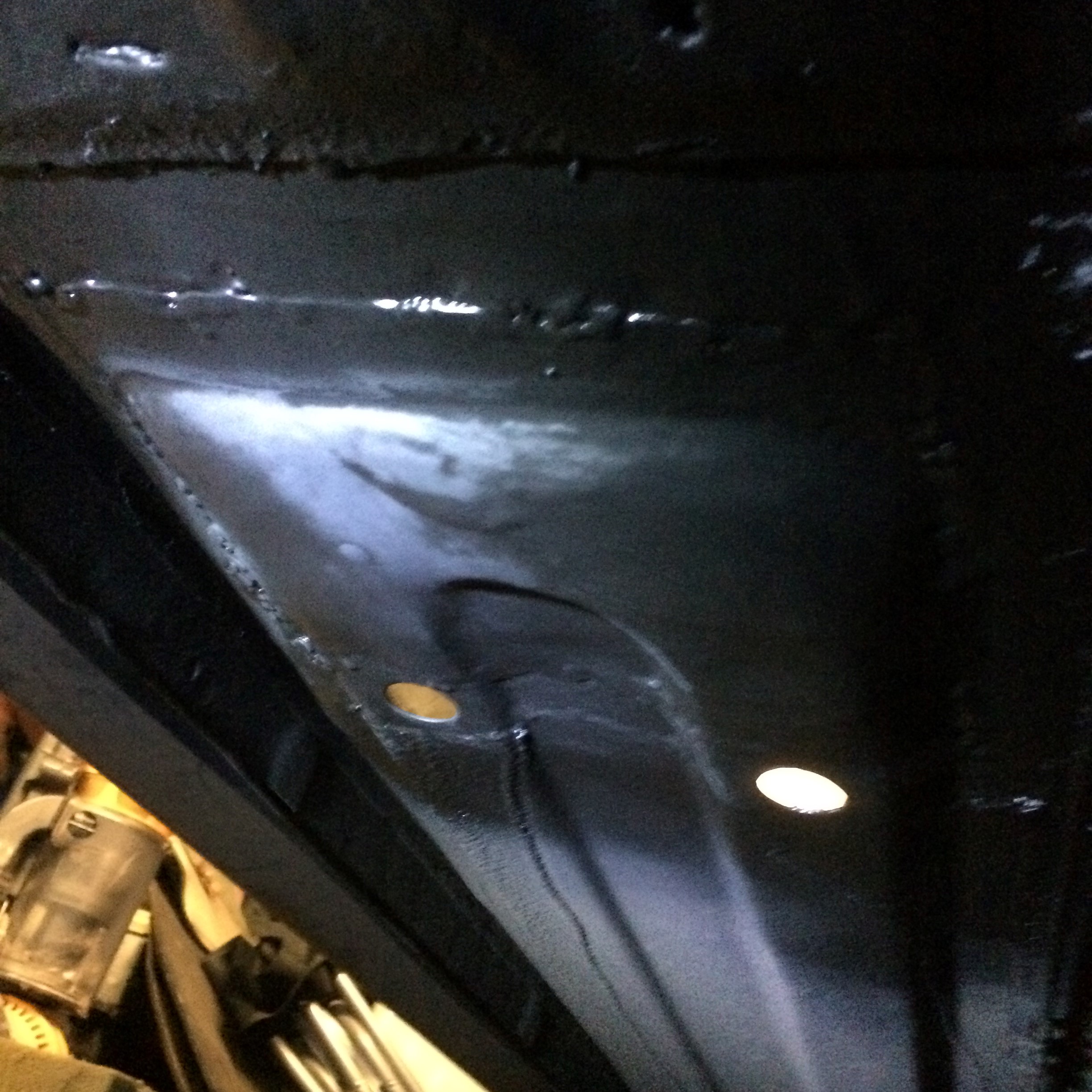
A coat of primer then a few coats of stone chip paint for the underside and some satin black inside finished it off quite nicely. It seemed prudent to spray in some wax protection into any cavity that was accessible at the time (sills and front of foot-well) There was some loose under-seal and paint around the front edge of the wheel arch. I removed the flaky paint/rust and also painted those areas with stone chip paint.
Front edge, loose under-seal removedPainted undersideFront edge cleaned up and painted
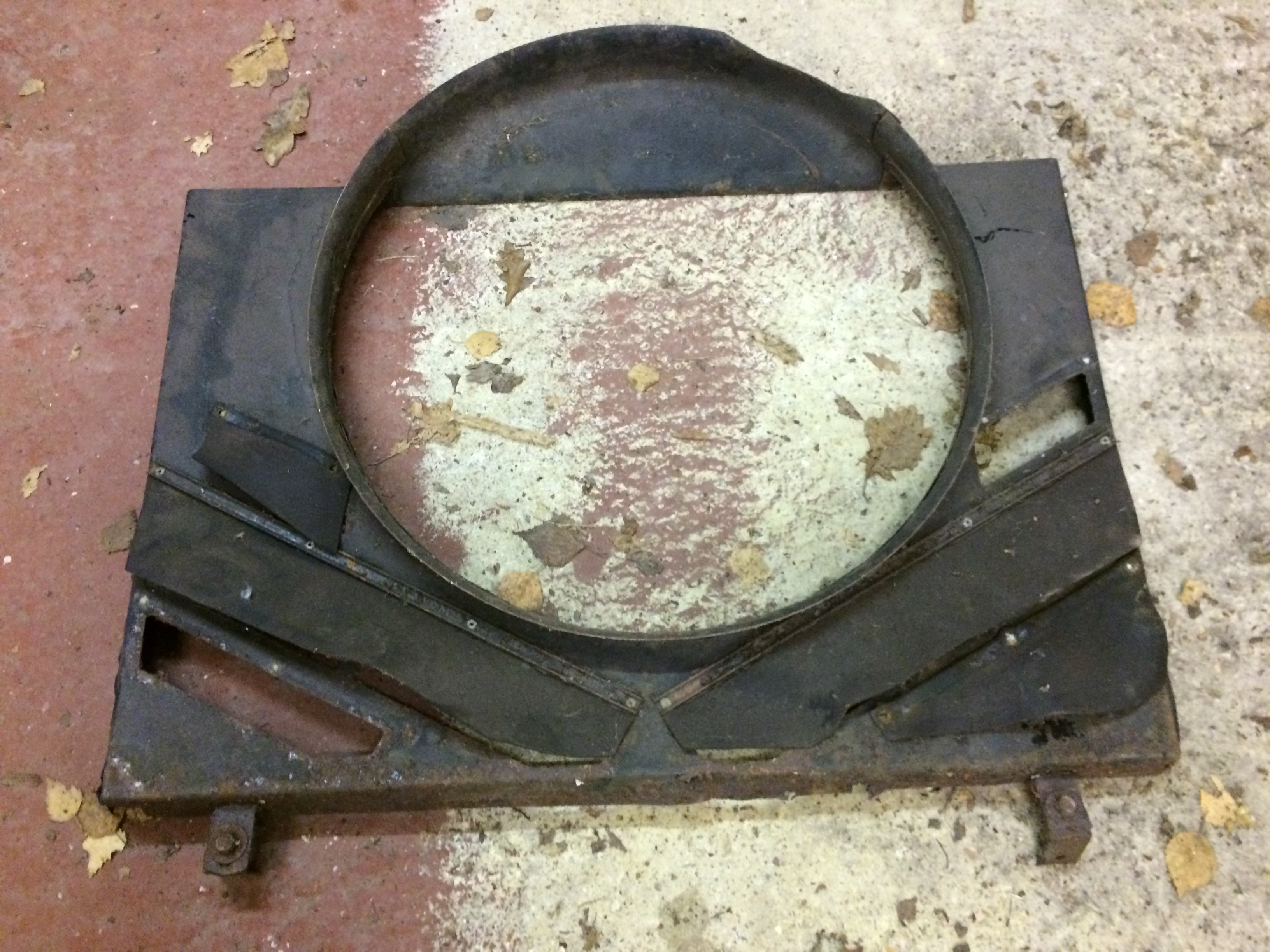
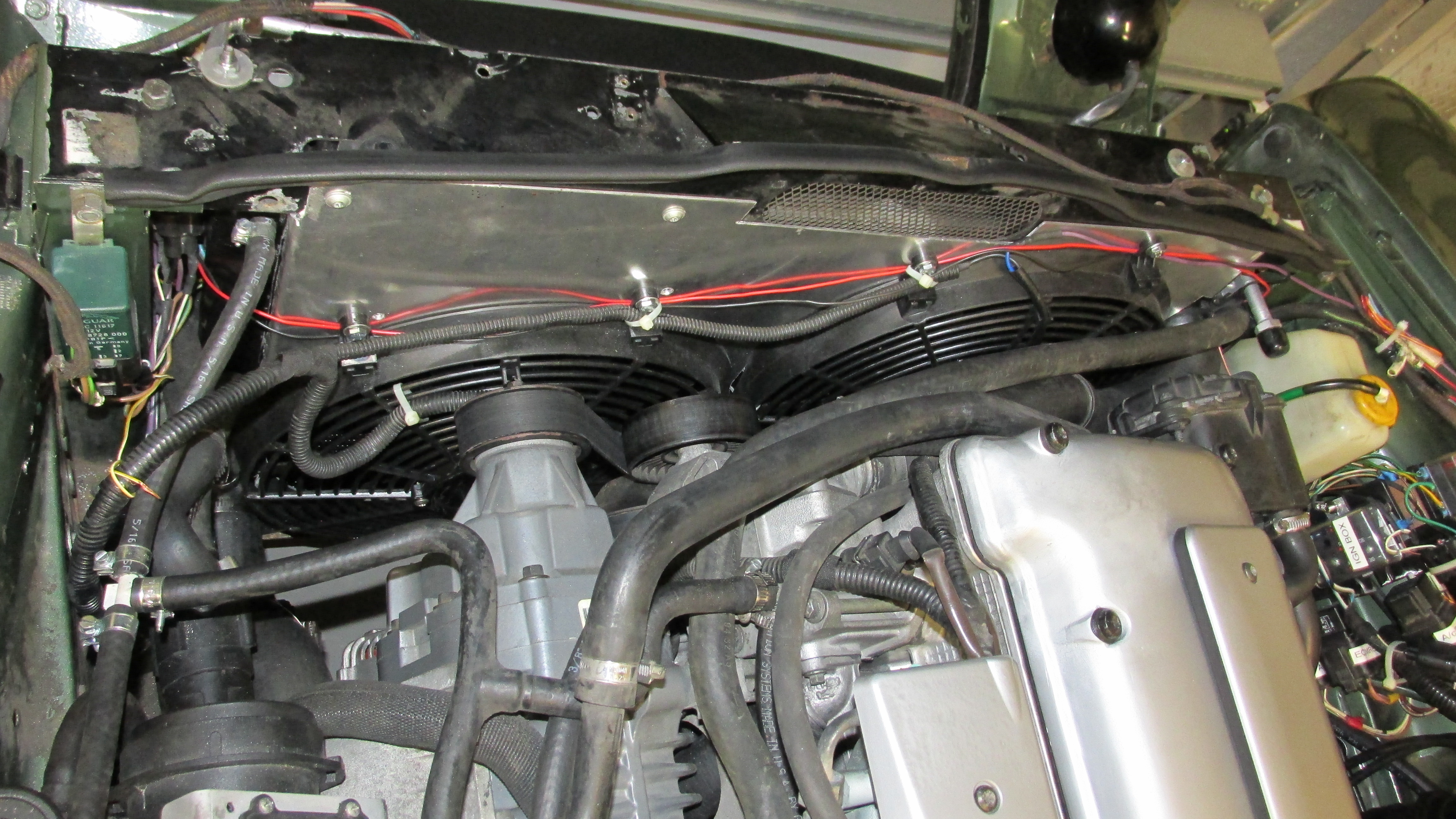
As previously mentioned, I needed to fabricate a new fan shroud for two reasons. First, the original XJR6 fan shroud had the fans mounted diagonally and they were too high to fit into the available space in the XJ6. Secondly they were to “thick” to fit flush where the standard fan shroud went. I did initially start with the old series 2 shroud, cut out and replaced the rusty parts and then started reshaping to fit the new two fans. Having spent quite some time on this process, I realised there was hardly anything left of the original S2 assembly and it was made up of multiple parts. The best thing to do was to throw it away and start from scratch. I used some of the steel I cut out of the bonnet of the XJR6 so it is made from Jaguar metal anyway 🙂
I should have made it entirely from one piece but I think it is OK with extra strengthening parts welded to the sides. As usual, these things evolve and if I was to make it again I would do a better job of it. The same goes for cutting away the plastic parts of the shroud assembly. Changing the design half way through has meant I cut a little too much away for the ideal final solution.
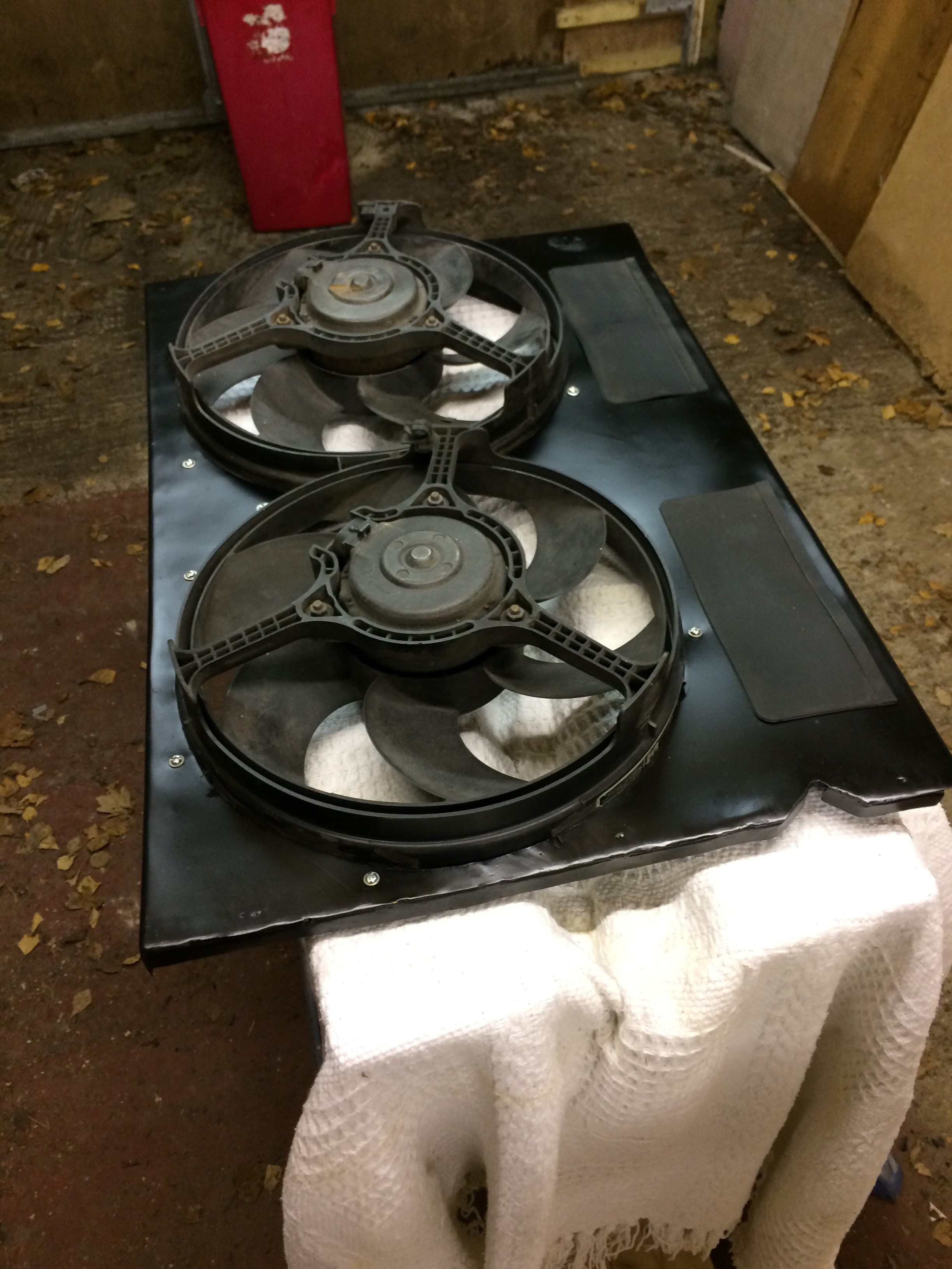
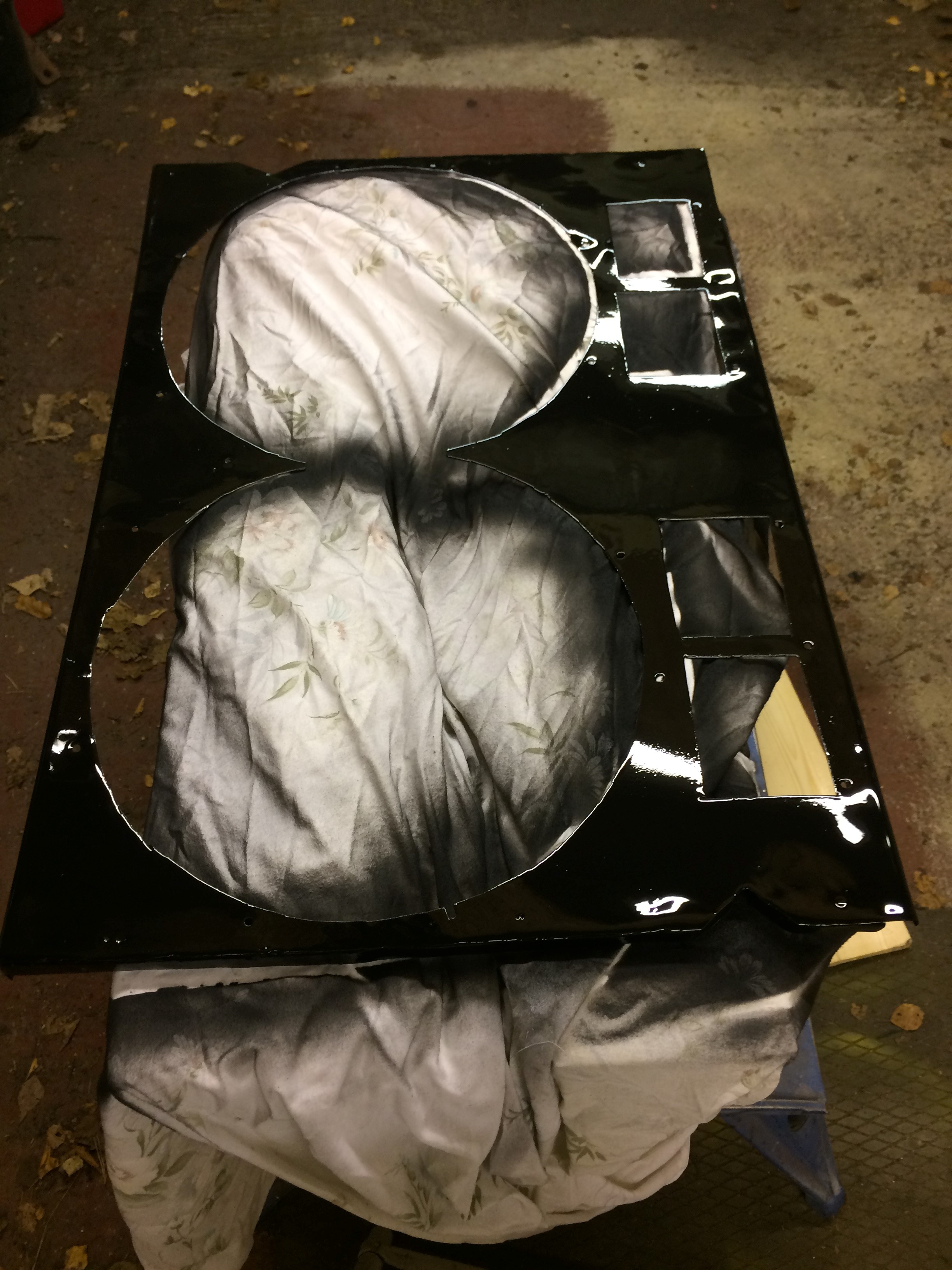
Fan shroud assembledJust painted Fan shroud
As you can see, the fans are now going to be mounted horizontally and I also cut out holes for the two rubber flaps using those from the original plastic XJR6 assembly. I did try to fit in part of the plastic molding around the two flaps as there was the word Jaguar molded into the frame and it would have added to the aesthetics even if it is under the bonnet. Unfortunately it would have been too big and I would only have had one flap in the centre too.
In the right hand picture you can see the finished, fully assembled shroud with the two fans and the two rubber flaps in place. The paint has a satin finish as I don’t like the mechanical parts all being gloss black.
Whilst I waited for the paint to dry between coats (primer then a couple of coats of black) I turned my attention to the header tank and the power steering fluid tank. I did look at a few options for the header tank. Finding a solution to the actual location took a little head scratching too. I decided that it would have to go on the left hand side of the engine bay (looking from the front). There is no space where the original went because that space is now taken up by the supercharger and associated piping. There is also the requirement to find a space for the power steering reservoir. On the series 2 XJ6, the reservoir is part of the power steering pump and mounted on the engine. On the XJR6, it is a stand alone reservoir which is mounted on the wing.
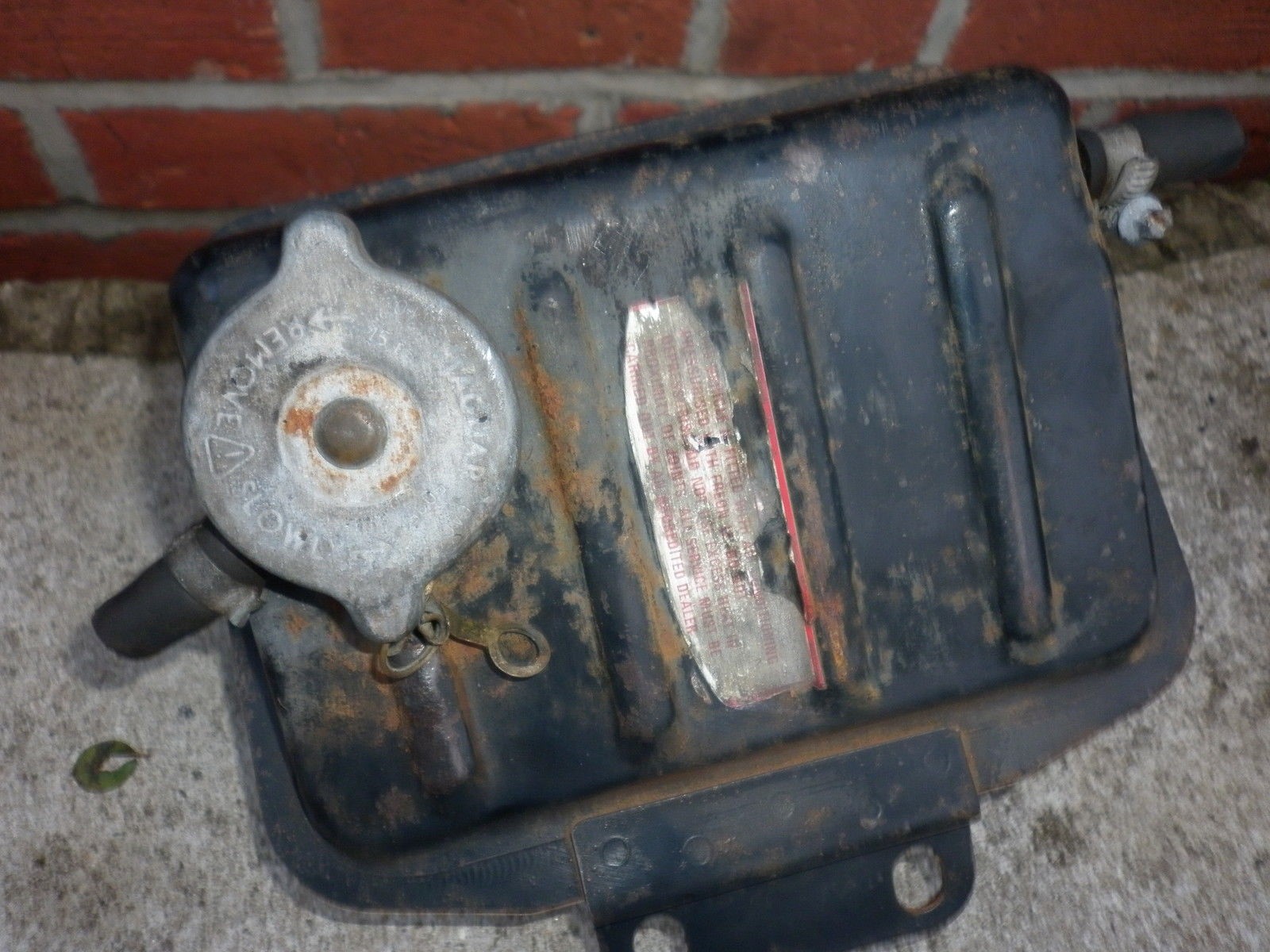
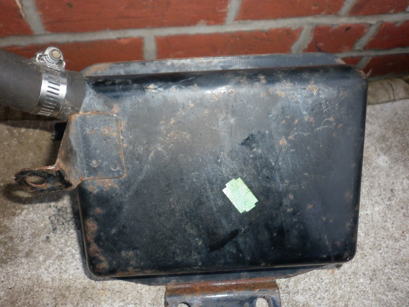
Reading the Jaguar forums, there was a recommendation to use an early XJS header tank. It is not too large and has mounting holes at an angle to be mounted on the wing. I did a little searching and found a second hand one on the well known auction site. There were three to choose from. One looked a little rusty, the other two looked better but all three would require cleaning and repainting.
As purchased (top view)As purchased (bottom View)
I chose the cheapest one which was about half the cost of the others but it sure did look the worst. As long as it was just surface rust and not all the way through then it would be fine. After a good going over with a wire brush wheel in my trusty angle grinder it was ready for paint. A couple of coats of primer and then the satin black and it looks fine.
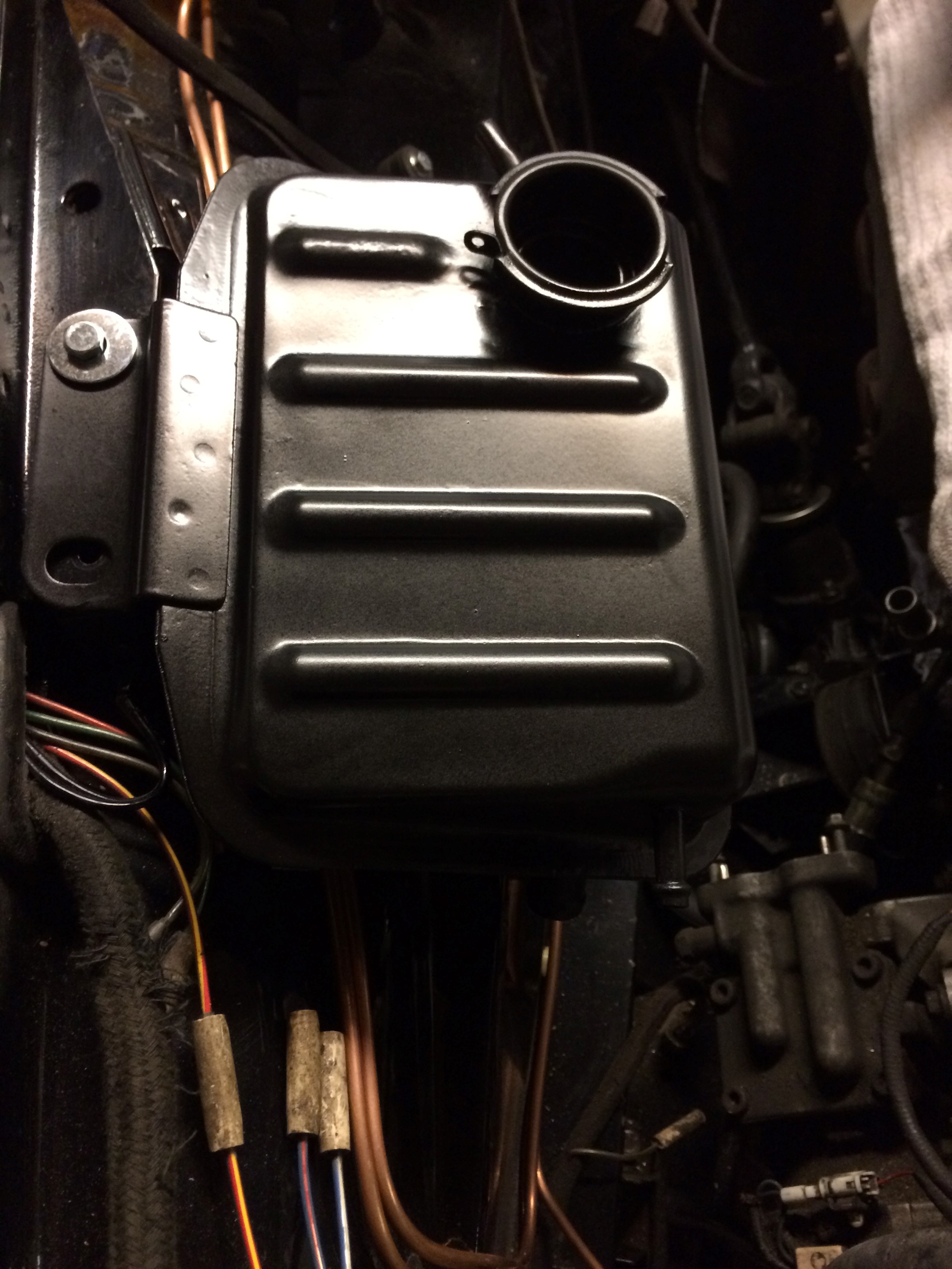
If I come across a safety sticker I might just put that on too. I decide to fit it on the mount next to the support braces that go diagonally across the engine bay. The other mounting is further down the wing and will be via one of the rubber mounts used for the air filter box on the XJS.
The picture below shows the final painted header tank with just one bolt pushed into the hole to hold it in place for the photo.
Fluid Reservoir locationPainted header tank
I had mocked up the location of the header tank and the reservoir so I deliberately left a small amount of space between the header tank and the brake master cylinder. I then spent a little while working out the piping for the power steering. It turns out, the old Series 2 high pressure pipes have the same fittings as the XJR6 power steering pump. There was an issue with the fixed metal parts of the pipes as I think they originally went over the right hand side of the steering rack tower and this would now be too close to the exhaust.
I think the exhaust pipe may hit the steering rack any way, so something else to tackle when I get to it. I happened to have a spare steering rack from an earlier XJ6 that had a different pipe layout. These were much closer fit to the rack and “U” shaped. That meant that I could run the pipes the other side of the steering rack tower and onto the pump/reservoir whilst avoiding close proximity to the exhaust pipes.
Another issue I worked on is that the cooling fans were controlled by a dual temperature switch mounted in the radiator. It turned on one or both fans based on temperature. The problem is, I am not using the XJR6 radiator so there is no where for the switch to go. I previously mentioned that although the original Series 2 radiator had a switch in it, the two radiators I now have do not. After a bit of searching, I came across the “Car Builder Solutions” web site and they have an aluminum housing for the M22 dual switch that goes inline with the large cooling pipe. The biggest they do is 38mm and so I will use reducers on both sides to fit. This is a slight reduction in diameter but hopefully will not cause an issue.
All of the above is ready to fit but as often happens, I ran out of time to assemble it.
If I don’t post before next week, I wish you a very Happy Christmas (or Holidays if your religion prefers) and a Happy New Year.
I only started this site a year ago and hoped to have the conversion completed way before now! Somehow, Life gets in the way sometimes and it has been a tough year for me personally. Hopefully 2017 will be a great one for me and for you too.
Decided to use the XJR AC set up as much as possible so ordered a new condenser and receiver dryer
I will have to have a couple of pipes made up to match the newer XJR pipes with the old evaporator unit in the S2 dash. I have both the old and new pipes so maybe get them cut and joined?
Decided to go with a reconditioned S2 radiator I purchased a few years ago (unless I can find the original and it is in OK condition)
Came across the size issue with the electric fans as described below but will probably do something similar to Larrys solution as per the link above
The issue with the radiator & electric fans on the XJR is that they are too high to fit into the space in the Series 2 XJ6. This means I need to use either a Series 2 or series 3 radiator and causes a number of issues as follows:
There are gearbox cooling pipes that screw into the XJR radiator where as the older S2 radiator used a tube that fitted into the large radiator pipes with the gearbox fluid running inside a collar. I seem to have mislaid that tube/collar too so I will probably have to buy a new one and change the pipes to fit. It might be better to go for a horizontal alloy cooler that I could fit in the front somewhere. Try searching for “universal 7 row cooler” to get an idea of what I am thinking of.
I have two radiators to chose from. One is old and rusty looking and will no doubt require a re-core and one all painted gloss black. I do remember purchasing the “reconditioned” one a few years ago. Neither of them have a fitting for a temperature sensor. This is a little confusing as I checked the older “tear down” pictures and I can clearly see a sensor in the lower right hand corner when looking from the engine bay at the radiator. I will have to hunt around and see if I can find the original radiator along with the gearbox cooler tube/collar.
Original Radiator & Temp Sensor ~ middle
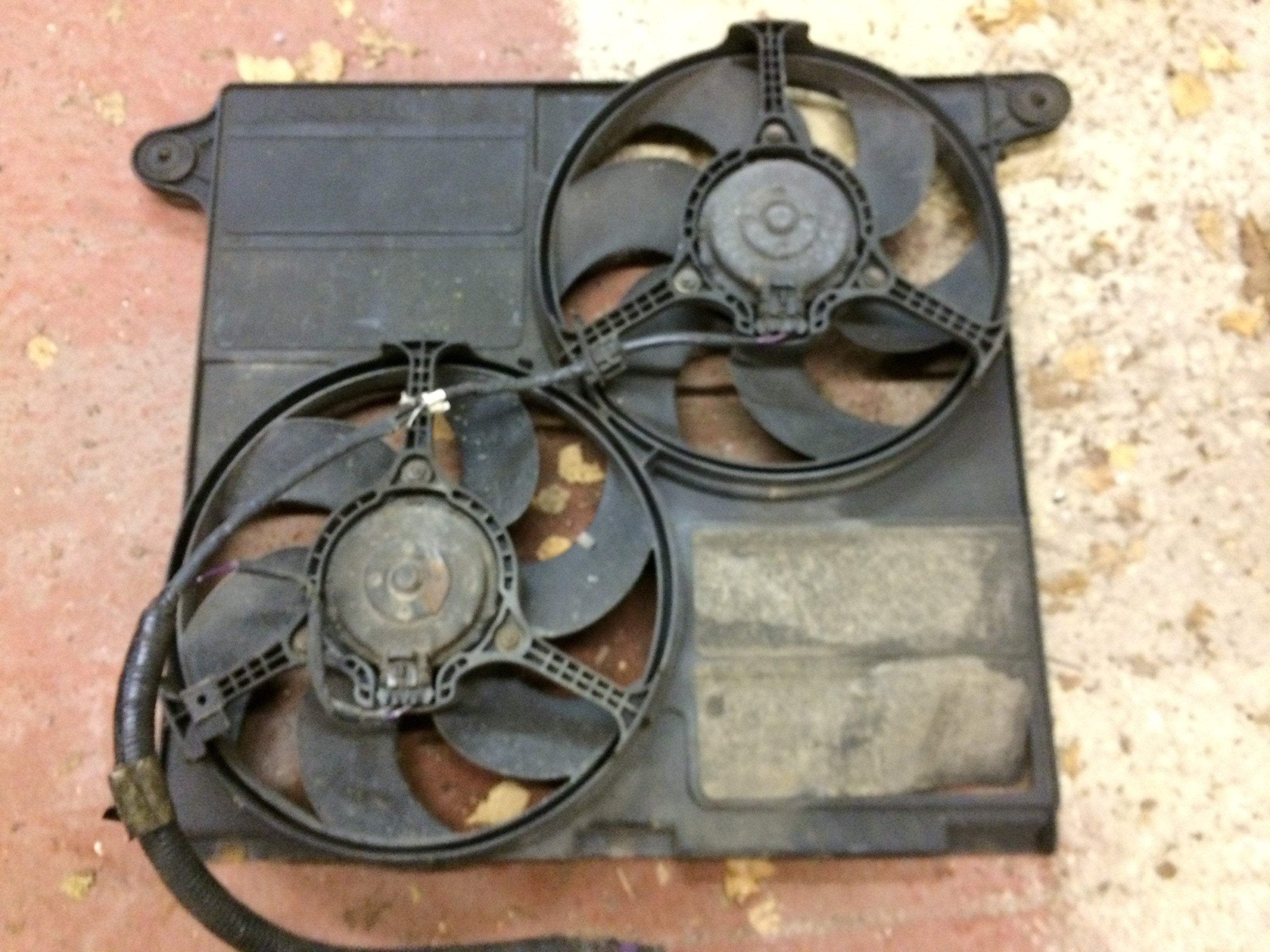
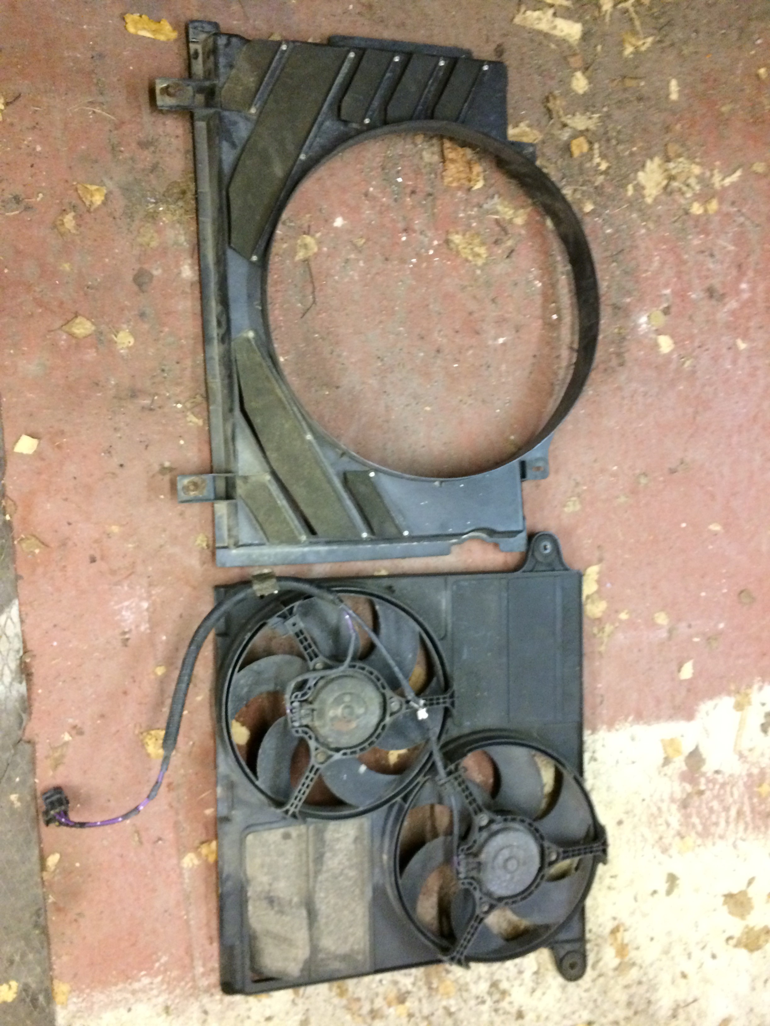
The XJR had electric fans so I need to have some form of electric fans on the new install. As you can see from the pictures below I have the original S2 fan shroud which is all tatty and rusty, A series 3 plastic surround which has the single fan cutout for the engine driven fan and the twin electric assembly from the XJR.
Original S2 fan shroud assemblyRusty original fan shroudRusty original fan shroudXJR dual electric fan assemblySpot the size issue 🙂
I plan to cut down the dual electric fan assembly and place them horizontally across the engine bay. This will decrease the height. Currently, I have cut across the bottom right hand corner (where the two lighter coloured flaps are in the photo) so it fits in at an angle but it looks terrible!
Larrys aluminum sheet design (on the jag forum) looks better so I will do something similar. During the rebuild I fitted a new front cross member due to it being rotted away. This means I can drill new holes to mount the radiator a little further towards the front of the car. That will give me a vital couple of extra centimeters providing more clearance between the new fans and the belts at the front of the engine.
Fun and games 🙂
Thanks to Larry Loudon on the Jaguar forum for the ideas and inspiration
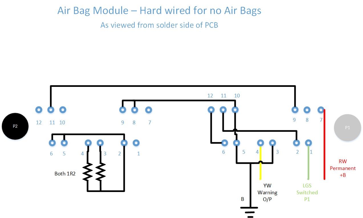
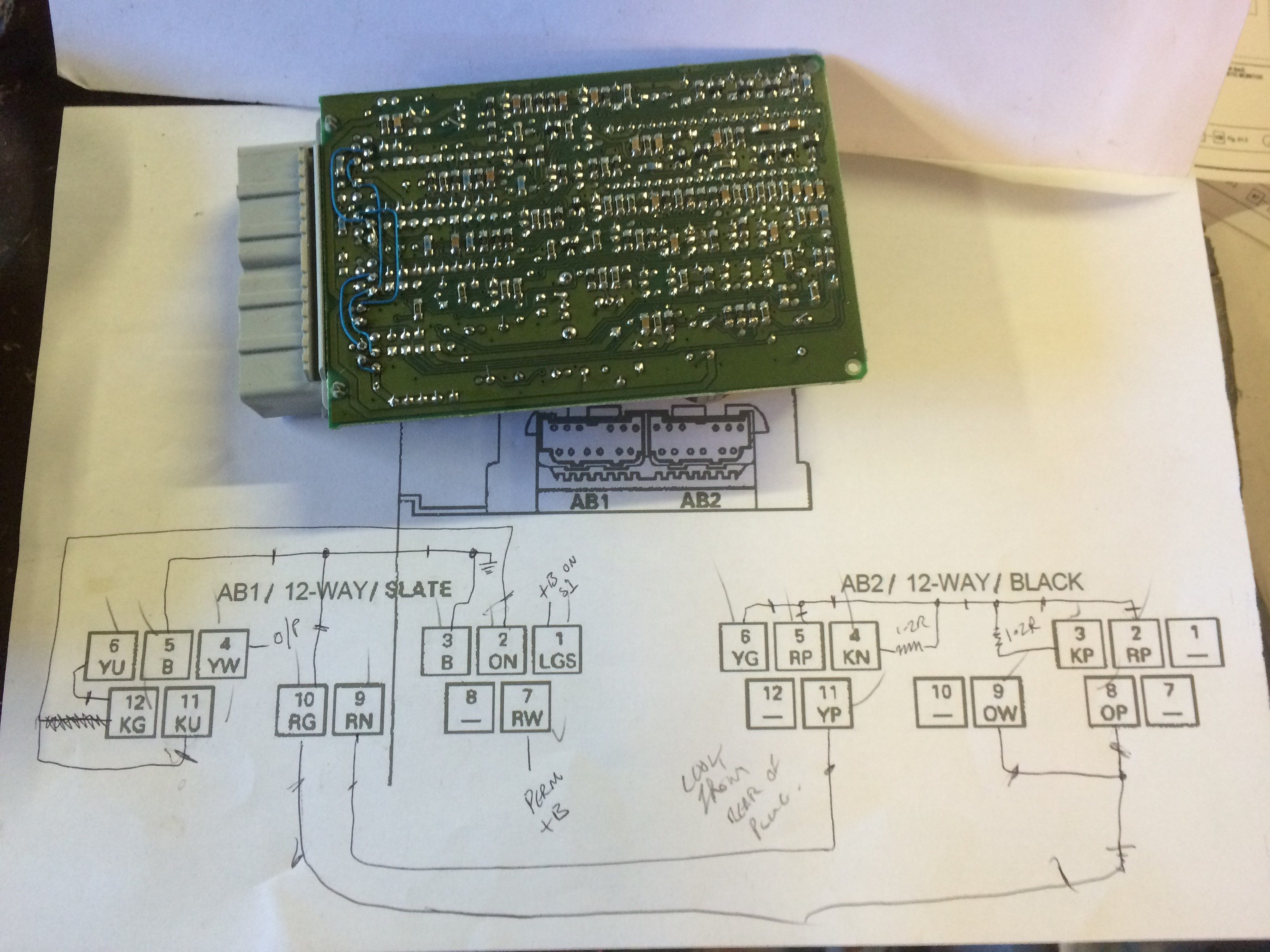
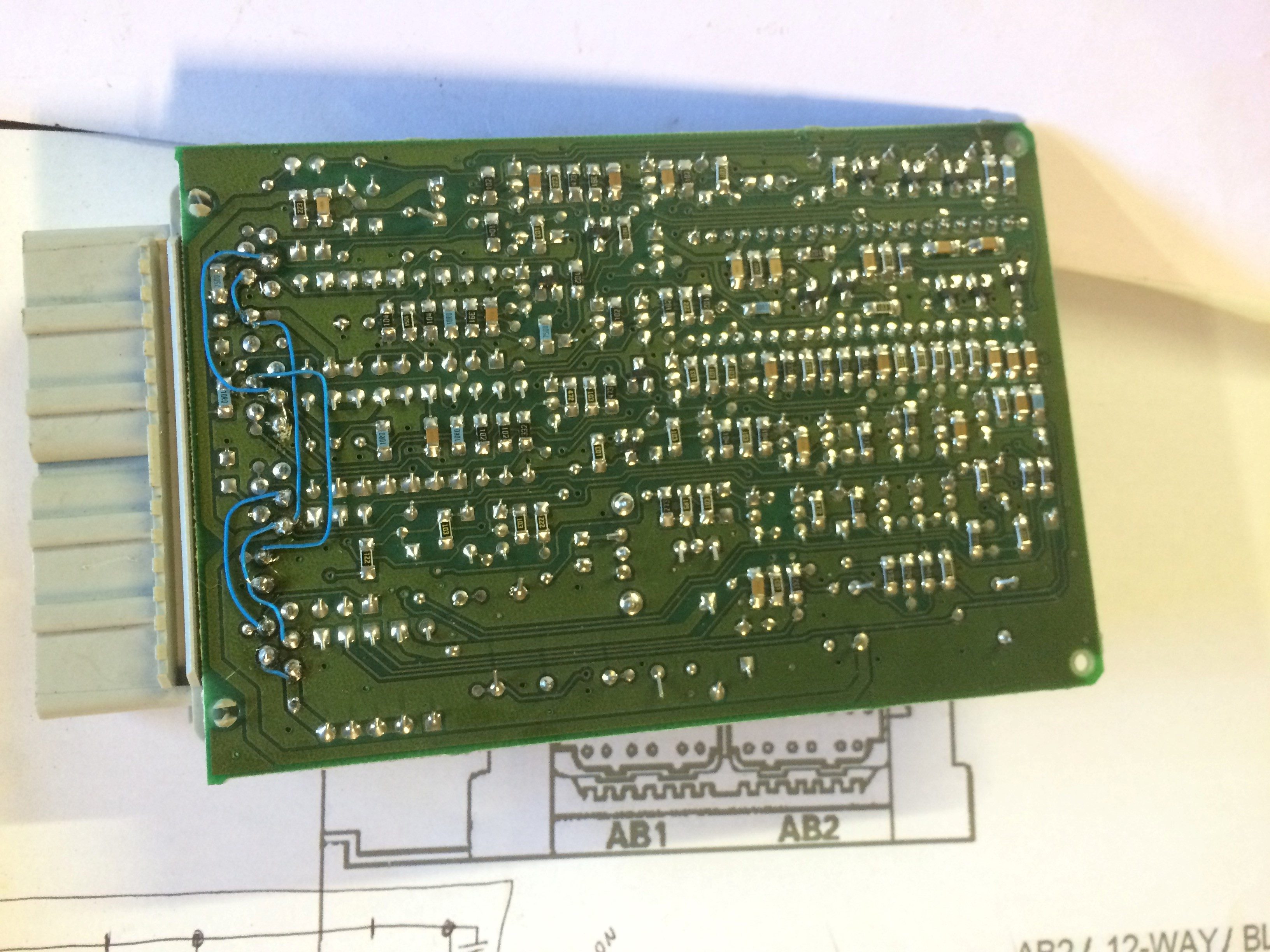
I have successfully wired the Airbag module into the car so it turns off the warning message and I can see the miles on the odometer. It will also stand a better chance of getting through an MOT now 🙂 I have drawn up the modifications if anyone else wants to do the same thing.
Hard wired for no airbags connected
Please note that the pin-outs for the modules in the electronic guide do not match the actual pin-outs on the module. The groups of three pins and two pins are interchanged. The diagram above show the view of the solder side of the circuit board.
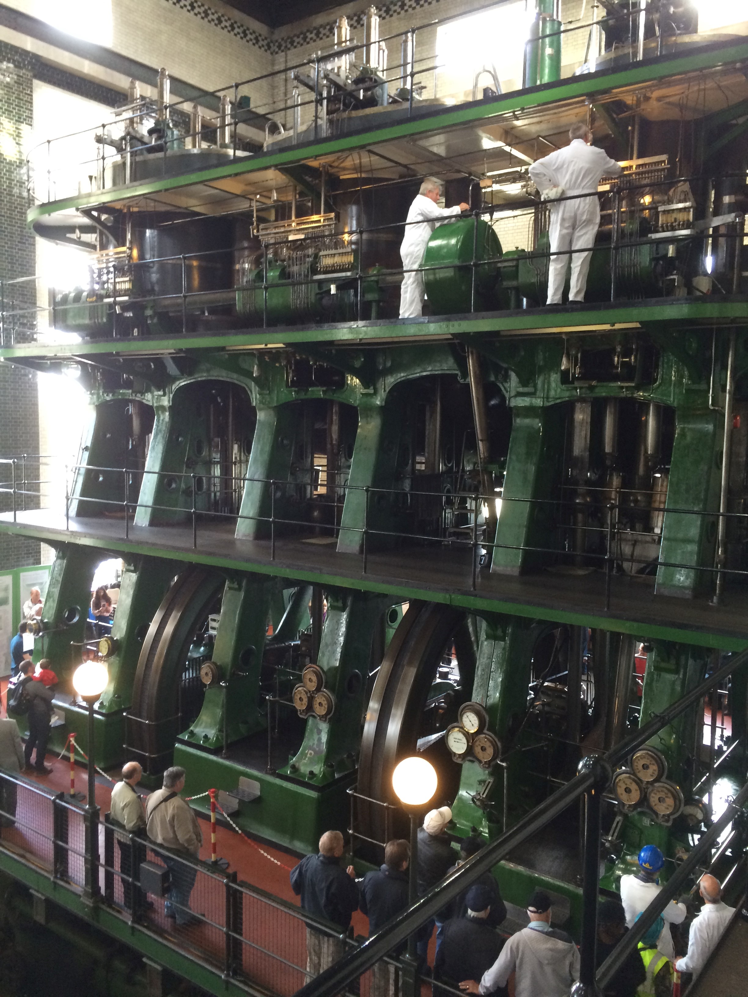
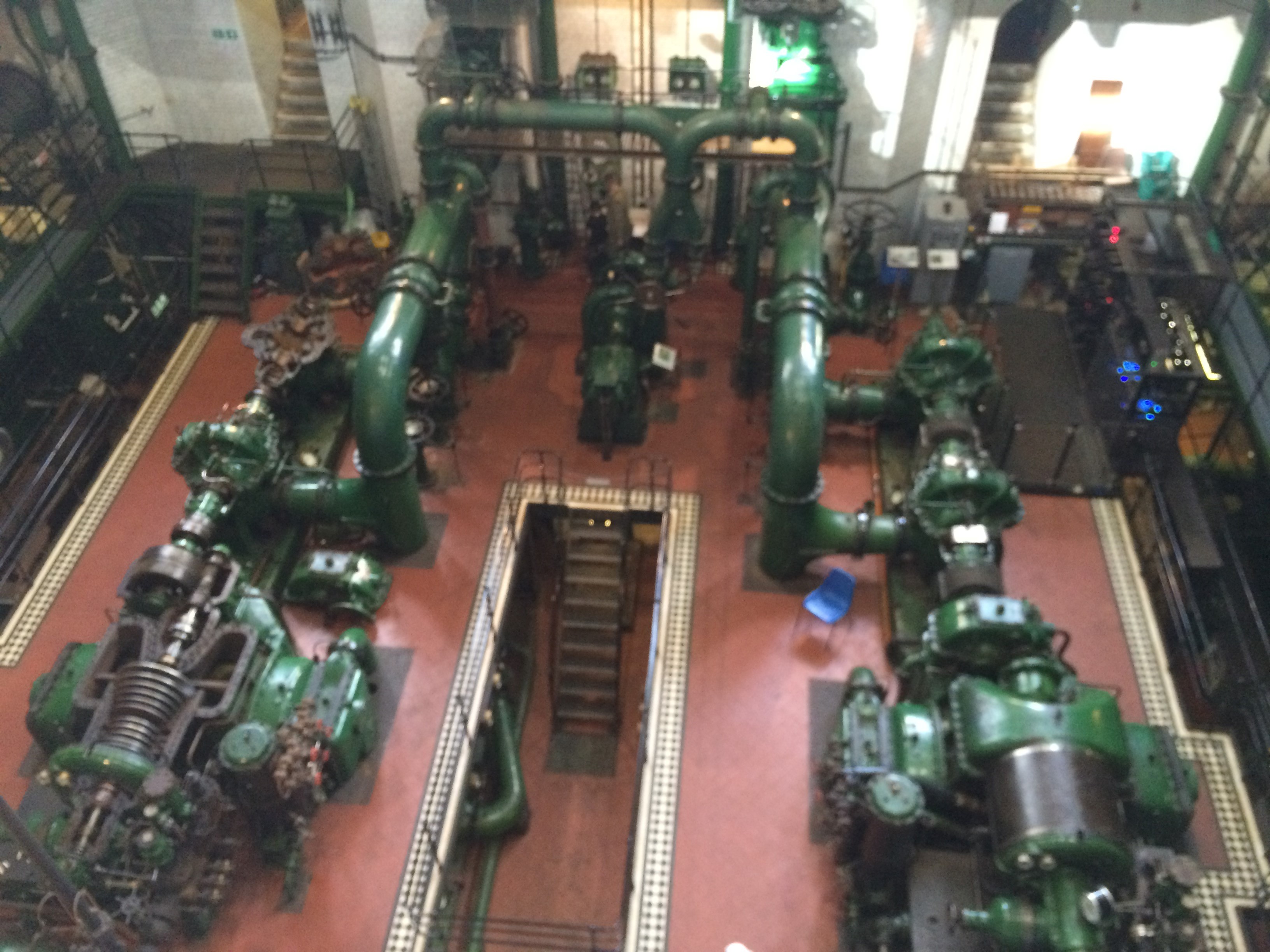
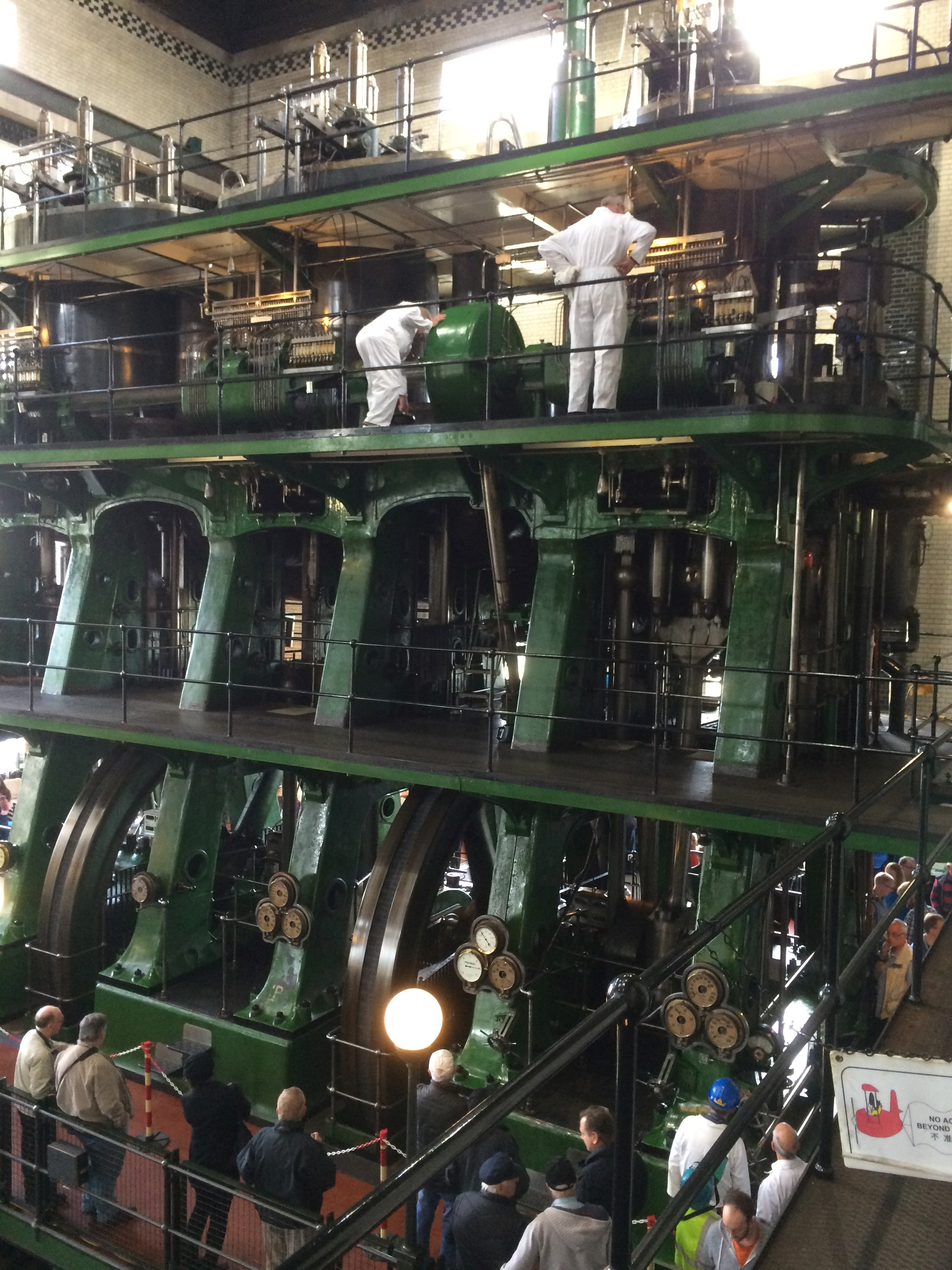
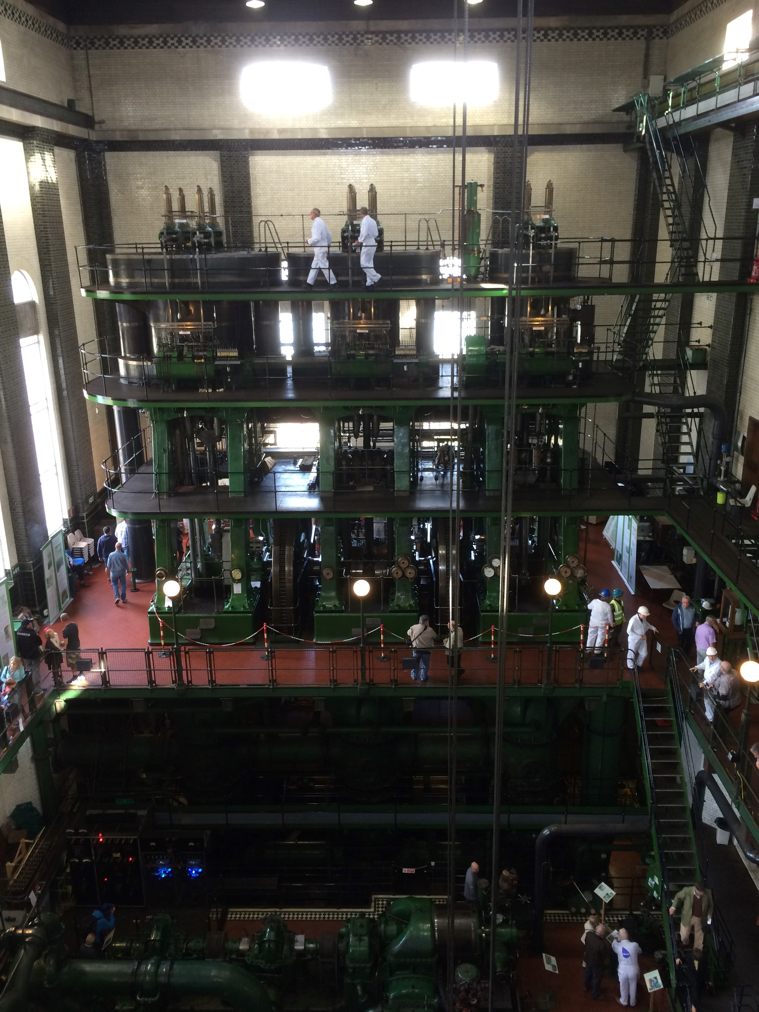
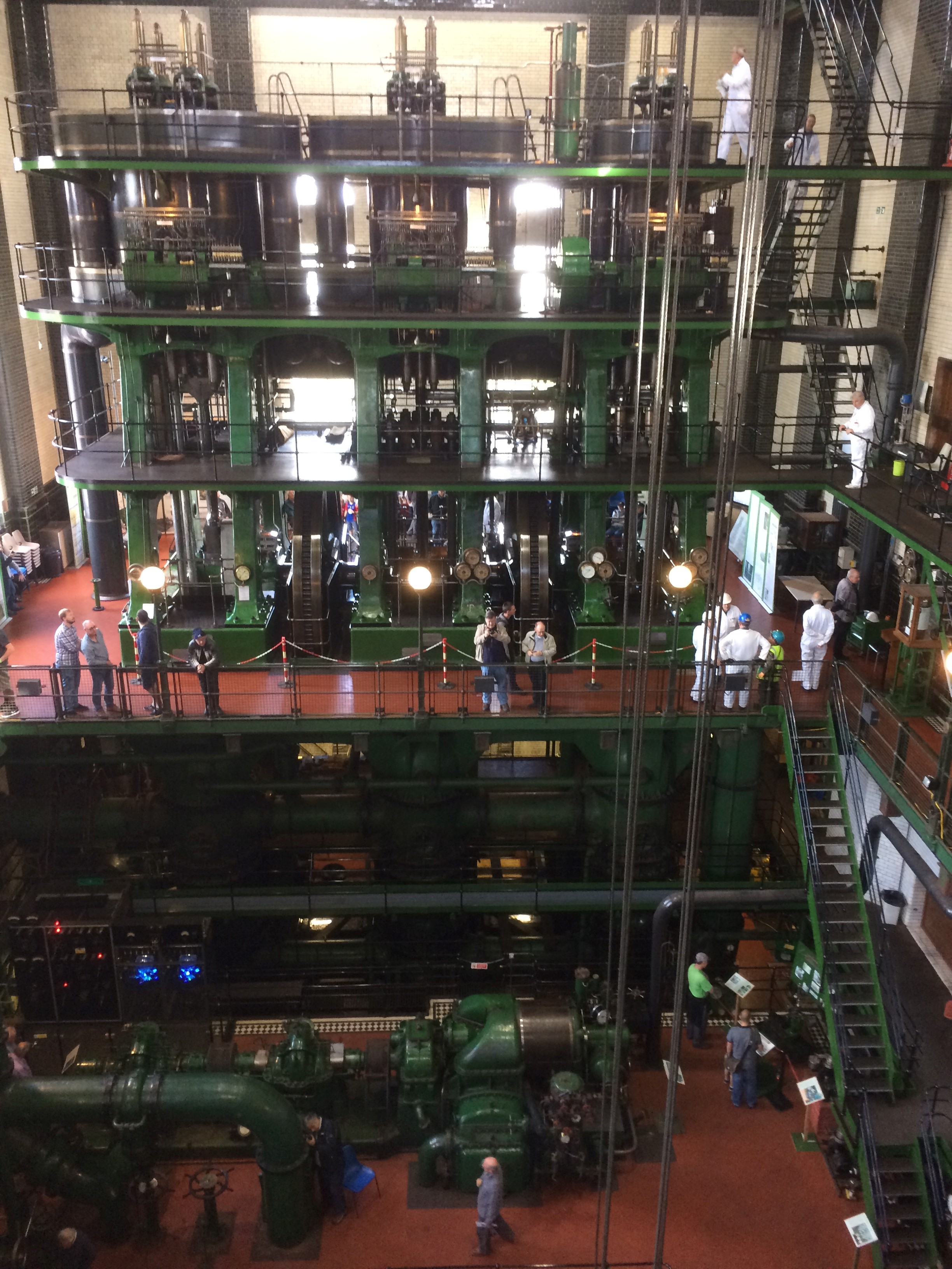
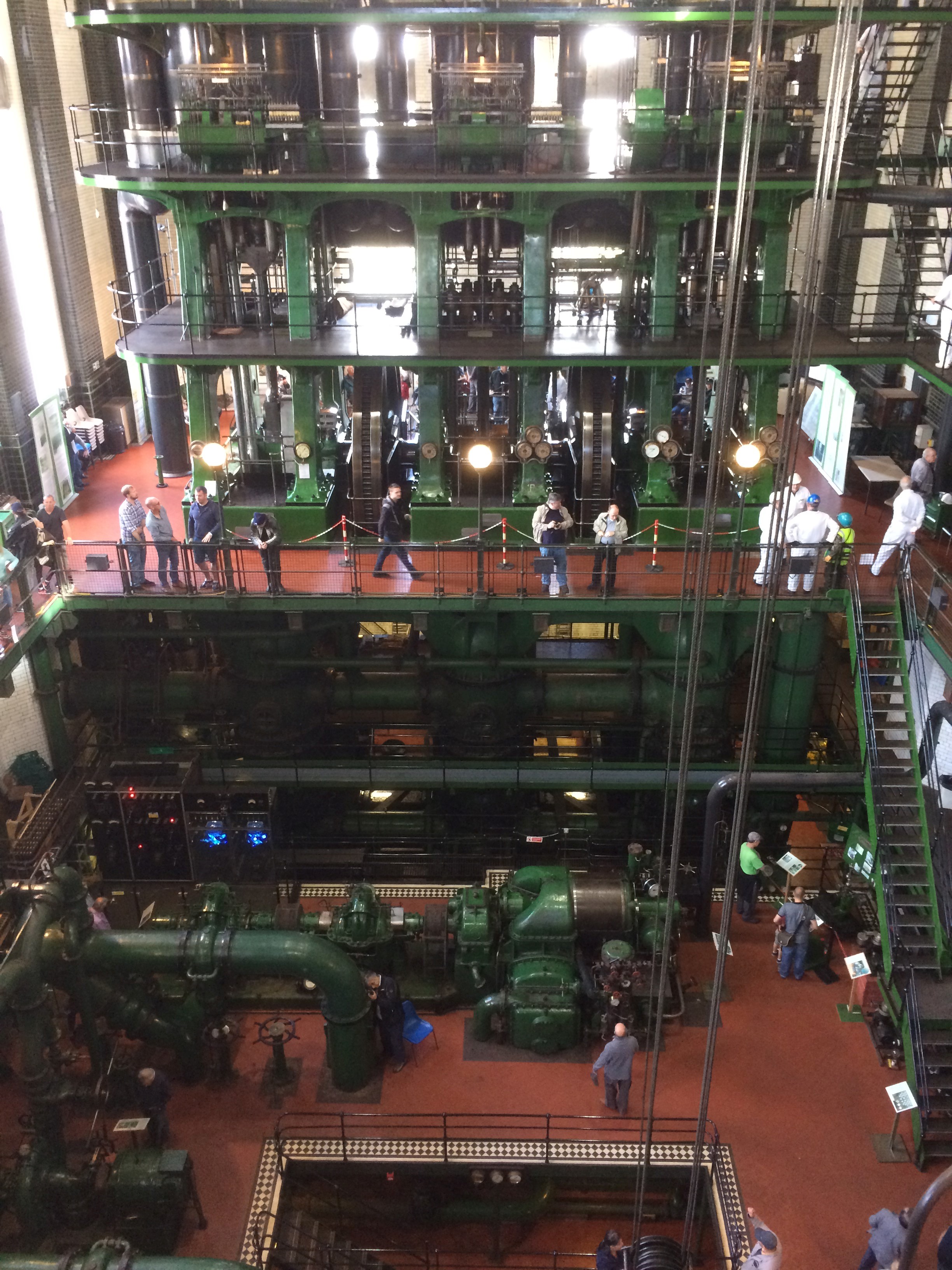
Visted the Kempton Steam Museum today. It was as really fascinating visit. I had been to see the engine run before but just the sheer size of these steam engines is enough to keep my attention. The building is listed and so are the Triple-Expansion Steam Engines. These are huge 3 story high team engines that used to pump ~33 million gallons of water per day to north London (15 miles). They did this for 57 years! The engines and the building have been restored by volunteers with some support from Thames Water (built a boiler house for them). Just an amazing achievement to get one of the engines running again. They are so huge and heavy, around 100 Tonnes, that they had to start warming the engine on Thursday for today’s run (Saturday)
They do guides tours, definitely recommended, tea/coffee and snacks (great value and good quality). Out side there is a Steam railway and a play area for kids. Today there was bit of a car show, Jaguars from the Surrey Hants Border JEC Club (Thanks for the lift and company Neil) and a range of other classic cars plus a long row of American classic cars too.
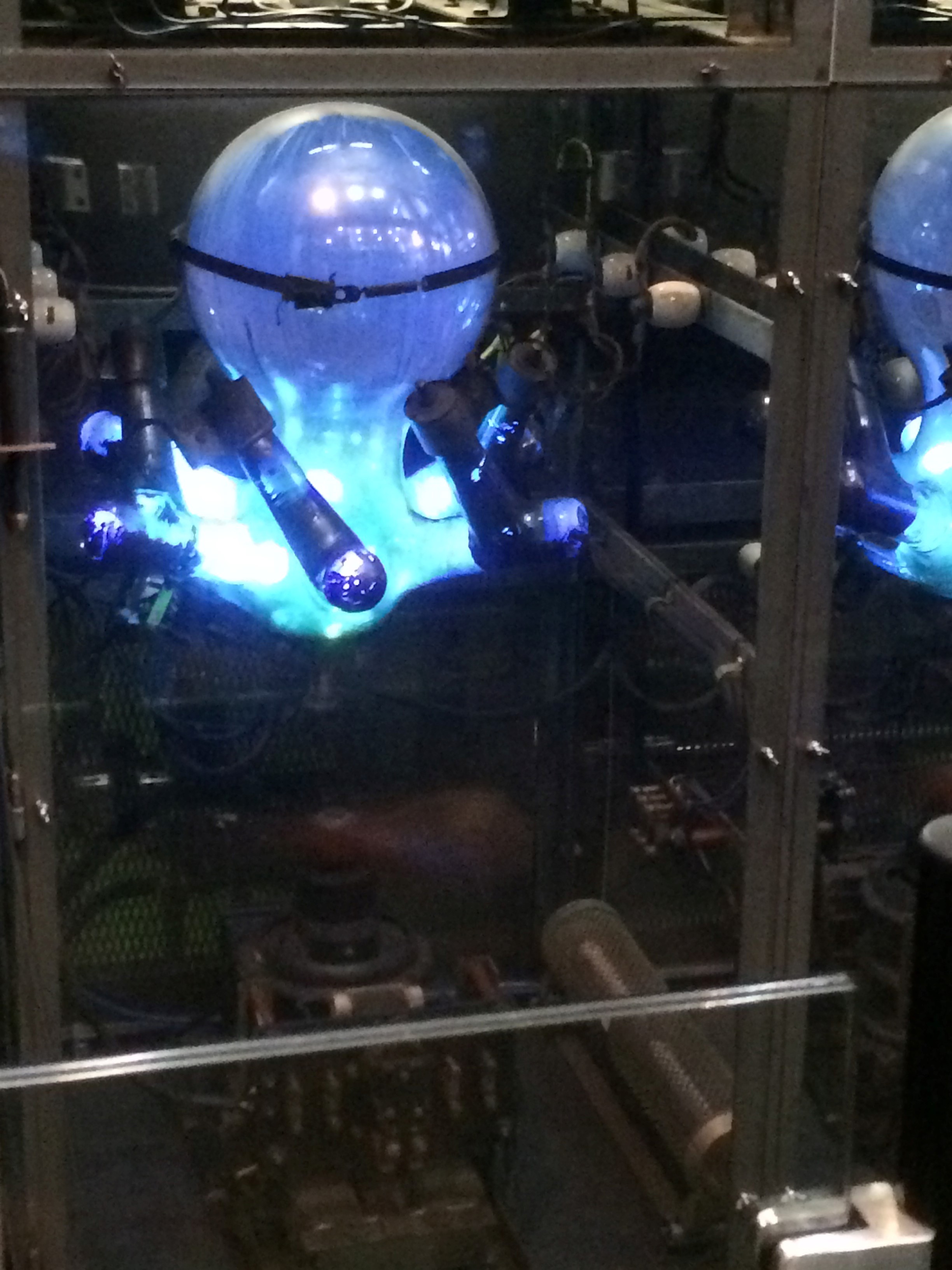
Engine Number 6Steam Turbine driven Water PumpsEngine Number 6 runningEngine number 6 running
These futuristic looking Glass Bulbs are actually AC to DC rectifiers (Diodes) They use Mercury as one contact and mains AC electricity is fed in whilst DC is the output. These are replacements and came from an Opera house of all places.
Following from the earlier success, I put the battery on charge which then limited further testing. The airbag module testing was complete however I had to make a choice. Modify the Air Bag Module (ABM) or build a circuit to fake the signal required. I decided that the quickest way to resolve the ABM output signal requirement was to hard wire the connections as if the airbags and impact sensors were connected. I will find a space for the ABM somewhere in the drivers side dash. Maybe to the right of the foot well just above the sill and under the air intake. I have put a second fuse box in that space on the passenger side.
I printed out the connector pin outs and drew the various links needed. This reminded me of having to do updates to circuit boards years ago but my eyesight was much better then! I still need to add the resistors to simulate the Airbags. There are no suitable resistors in my spares box so I will order some ASAP.
Air Bag Module and Pin outs
The blue wires are those I added to the module as drawn in above
Hardwired Links on Air Bag Module – click for a closeup
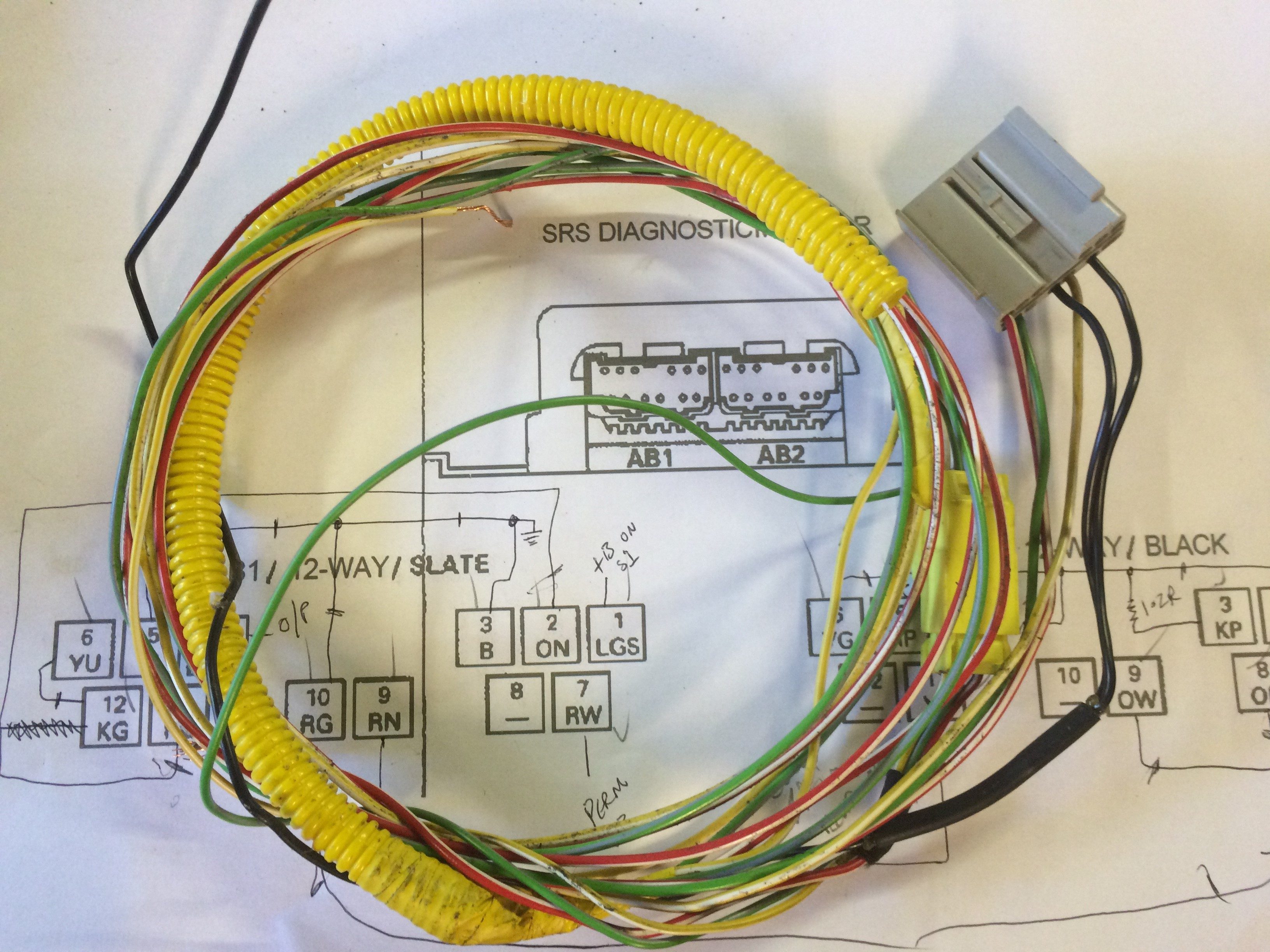
Loom requirements
The loom is much simpler now. The original loom is used with the unused wires removed. Only one of the two plugs are needed now so I will use the empty plug to fill the open socket and seal the wire entries with some sealant or glue.
The following wires are needed:
Two ground connections that go into 1 after a few inches
Continuous +B power
Switched +B power (ignition switch position 1)
Air Bag module signal output
I just need to order the resistors to finish the job.
I have just turned the engine over using the original S2 ignition switch! That might not sound much but what it actually means is that the Security and Control Module, the Body Processor, the Exciter/Reader, the XJR key, the ECU and a few switches and relays have all agreed that it is OK to turn the engine over. The engine immobiliser circuit is accepting the new setup.
Overjoyed at this moment. Still a huge journey ahead but a major hurdle overcome.
I did paste a little update on the Jaguar forum but I will paste a full explanation later as I want to check out a few other things.
Following on from my previous post on the airbag warning message, I did some testing of the Air bag Module (ABM) today. I identified the correct output signal that the Instrument panel expects following a “power on” of the ignition system. First, I used the original, yellow sheathed Airbag wiring loom and some resistors to fake the existence of Airbags. It turns out that the steering wheel Airbag reads approximately 1.2 ohms when in good condition.
WARNING!
Please be very careful when doing anything with “live” Airbags, they are dangerous hence I used resistors instead. Please, Please view any one of a number of videos available on the subject at the well known online video site prior to connecting anything electrical to an Airbag. If you do not know what you are doing, get someone who does. I suggest you do not touch them at all. I have measured mine so you don’t have too. Just keep them locked away somewhere safe or dispose of them safely. Do not come back to me of one goes off accidentally, you have been warned!
I did not have any 1.2R resistors. I ended up using four 6R resistors in parallel and just pushed them into the appropriate plug in the loom. It took a little debugging to stop the Airbag module from buzzing an error code. Once I had the rig working, I could see what the output signal should be in normal operation. The issue I had was that the Safing module does not have a separate wire for its ground connection. It relies on the connection to the chassis via the mounting bolts. As I had the module sitting on a wooden panel, I needed to provide it with a separate ground to get it working.
Airbag Module Test Rig
As expected, it turns out that although the circuit diagram says Ground and +B as the active/inactive conditions the reality is a little more complex than that.
With power permanently applied to the module the output signal is +B
Turn on the ignition power and the signal drops to ground for approximately 10 seconds
This is the Self test Pass signal “sequence” I was unaware of prior to this test
After that, the signal returns to +B and remains there unless an error is identified
I did try disconnecting the resistor packs (pretending to be the Airbags) one at a time and the signal goes from high to low as follows:
3 times high to low
A short pause at high
Followed by either two or three high to low again depending on which “airbag” (actually a resistor pack) was disconnected
It then repeats the sequence again until the problem is resolved
This, I presume, equates to error codes 32 or 33 which is similar to the way the error code was displayed by the ABS module on my old XJS. It flashed the ABS light on the dashboard after you shorted a couple of pins together on the ABS module
The question is now, do I generate the same signals using just a few components or do I hard wire the required signals and use the Airbag module?
Debugging the Transmission MIL light
Having identified the requirements to resolve the AIRBAG warning on the digital display. It was time to look into the Transmission MIL light issue. First there was the connection of the transmission loom to the transmission control module. I removed the panel below the gear leaver assembly which enabled me to push the transmission wiring connectors through a hole in the tunnel and connect up to the transmission module. The transmission error light was still taunting me! I did a slight tidy up of the wiring and re-connection of the Transmission module ground but still had the error. A little more debugging and discovered that I had not connected the permanent power feed to the transmission control module. I connected this up to the appropriate permanent feed, the MIL light went away.


