Jaguar Related

Base Jaguar home page

XJ6R – Airbag warning debugging

Airbag warning debugging

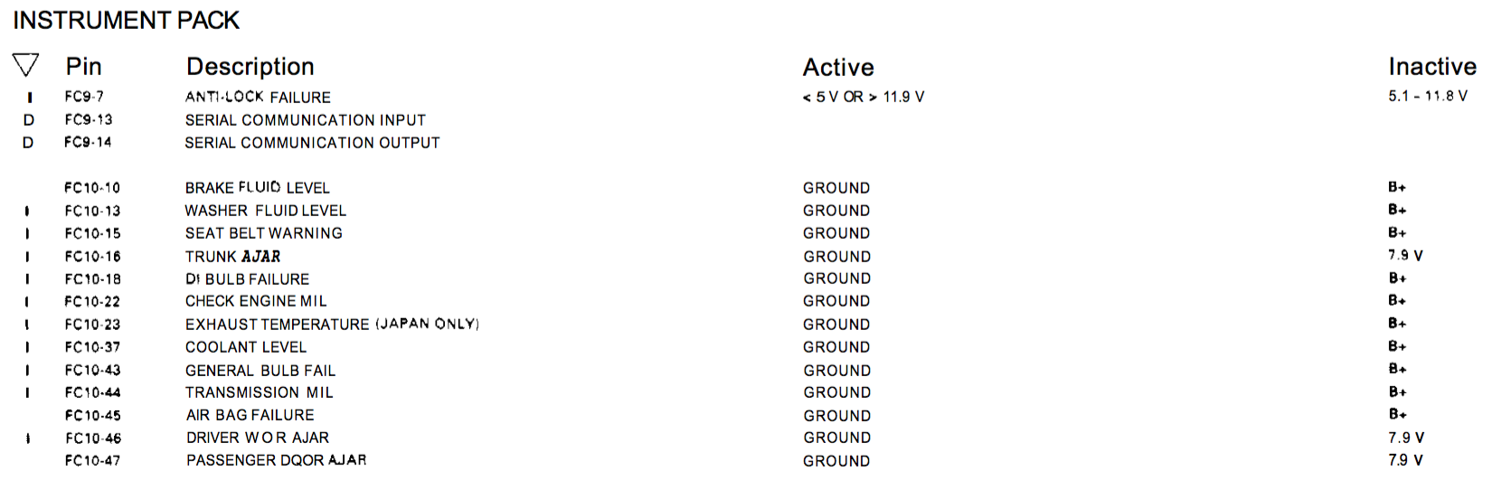
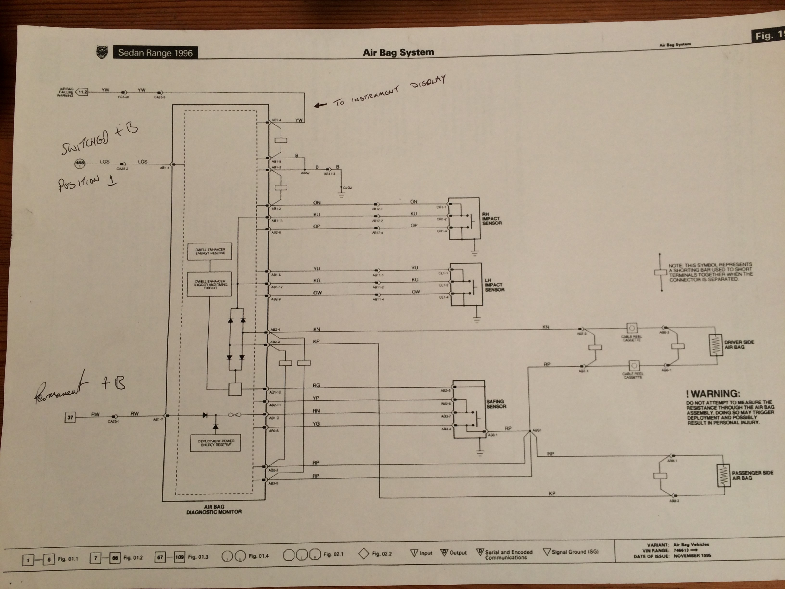
This post follows on from the last post where I explained the issue I was having when attempting to use the digital display from the XJR6. The display was showing the mileage then FLUID and AIRBAG messages. Having shorted the appropriate input to ground for the engine coolant sensor the FLUID message went away leaving me with the AIRBAG message to resolve. I tried shorting to ground or +B on the appropriate input but nothing seemed to clear the message. A photo of the Airbag circuit diagram is below, click for a larger version.

oldr 593

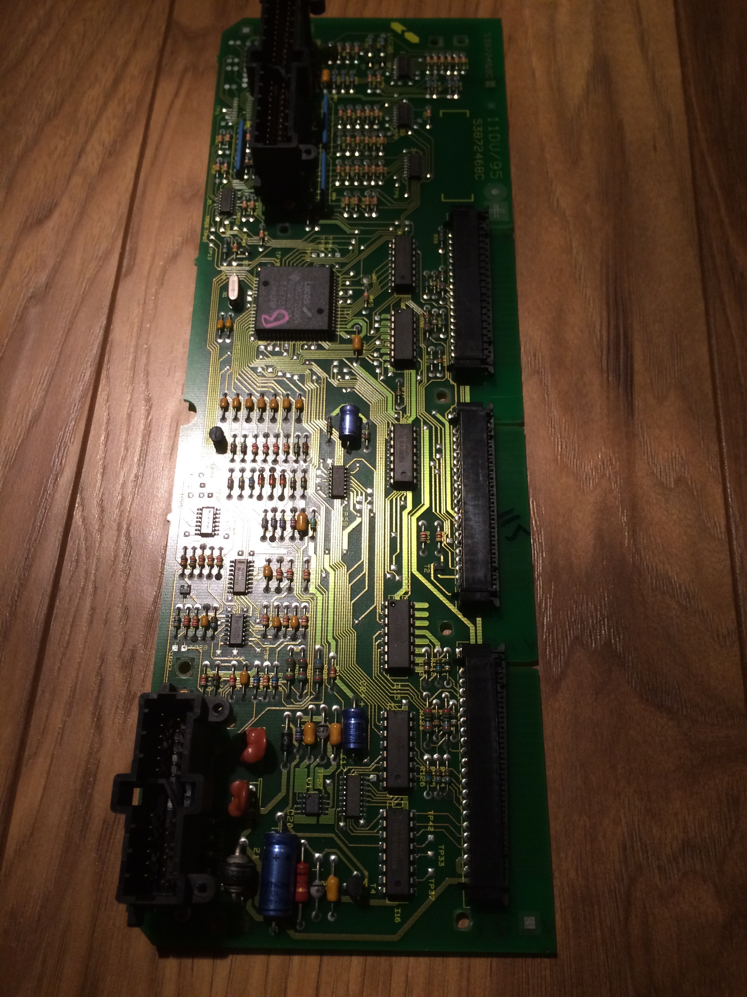
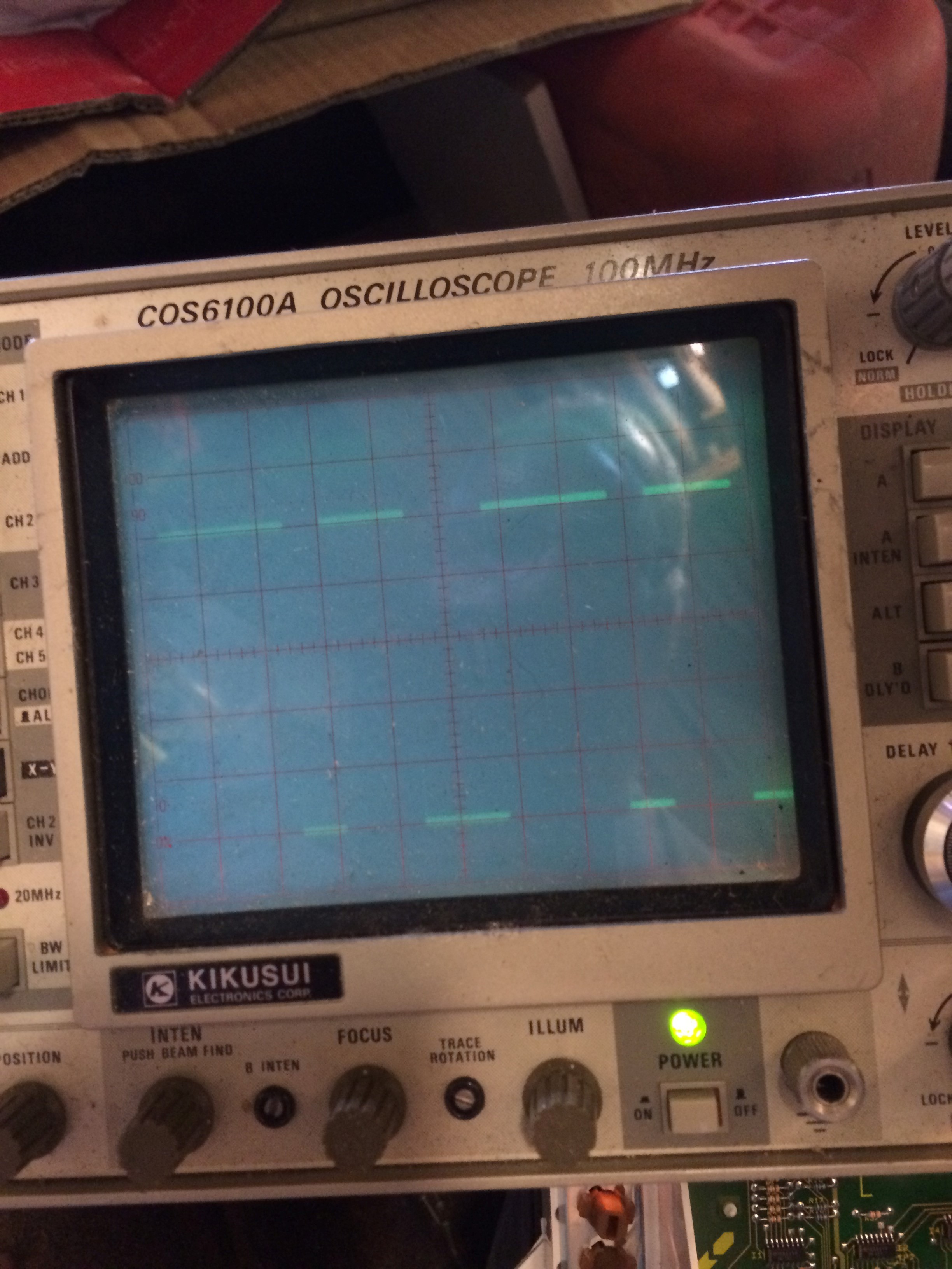
Since that time I have done a little more debugging. I proved that the feed to the main processor in the instrument circuit was receiving different signals depending on the status of the signal that should come from the Airbag Module. The Instrument display circuit, therefore appears to be receiving the appropriate signals to turn off the error message but it is not. The signals on the “Y” output of the HC151 chips looked like below with the signal grounded or at +B so you can see there is a difference and it was being propagated through the circuit board.

Signal with input high
Signal with input low
Signal with input low (airbag failure light should be off)

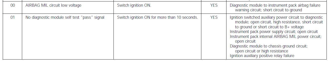
A little more research showed that there is potentially an error message generated due to “No diagnostic module selftest Pass signal”. Does that mean that there is a short signal sequence that is emitted from the Airbag module after power on that the Instrument circuit is expecting? There is no clock signal synchronization between the two modules so it has to be pretty basic pattern. I suspect something like a high signal initially and then low for maybe a second or two in each state. I really don’t want to have to add the Airbag module into the car. Using a test rig is needed to see if I can work out the signal states for the Airbag module in normal operation. Hopefully a very simple workaround can be found other than actually adding yet another module into the car ;-(


Airbag error codes
Airbag error codes

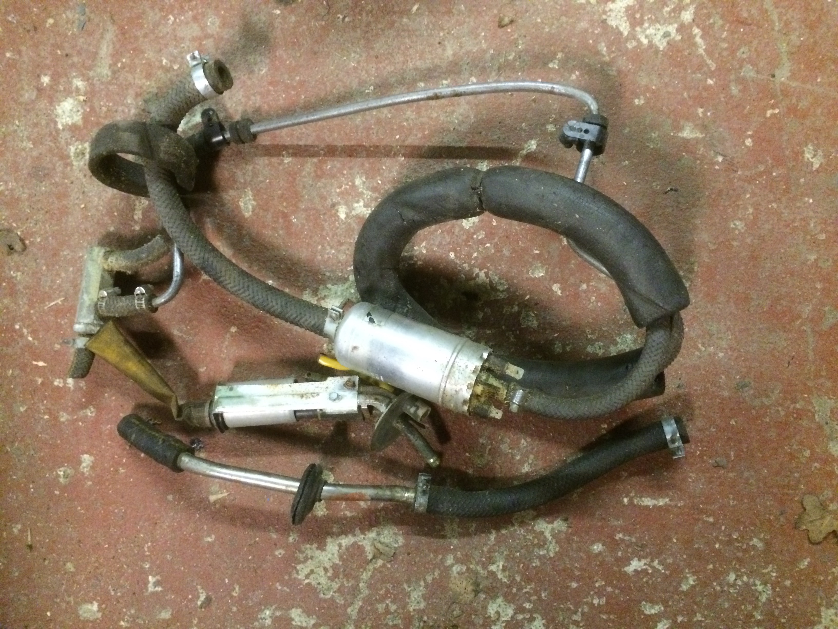
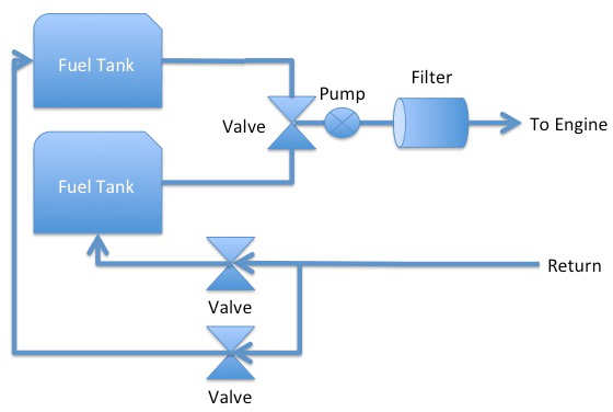
The Airbag module has a single output signal (Airbag Failure Warning, connector AB1, pin 4). The manual states this is either ground or +B.  It does not have any other connections to the CAN bus or directly to any other module. The only connections are to the two impact sensors, the Safing sensor and the airbags themselves. Doing a little research, it appears that Airbags have a resistance of around 2-3 Ohms each. This should be replicated rather than actually connecting the Airbags to the module along with the potential safety implications! I still have the full Airbag system wiring loom along with one of the impact sensors and the Safing module. I will use this as the test setup and fake the actual airbag connections to identify what the “Selftest Pass” signal looks like.

This will dictate one of three possible outcomes:

  1.  Replaced the module by a very basic circuit to replicate the required initial signal(s) required to stop the error message
  2. I will fit the Airbag module in the car just to eradicate the error message and allow the use of the XJR6 digital milometer
  3. I will not use the digital display from the XJR6 to provide a milometer and use something else like a GPS based milometer instead.

Next post when I have solved it or given up!

Le Mans Classic 2016

Le Mans Classic 2016

I spent the last few days at the Le Mans Classic event. It is a great event and I actually prefer it over the real 24h race.

The journey really starts to get interesting as soon as you get near a ferry port or the channel tunnel. All sorts of classic cars on the roads eventually arriving and producing great views at the waiting areas to board.

IMG_2705 IMG_2704 IMG_2703

Then there is a quick look around on the ferry followed by the tedious crossing.

Stops for Fuel and the obligatory nature breaks on the way

IMG_2709 IMG_2708 IMG_2707

But once you are there things really get good!

Loved this Buick and Caravan

Then just a mixture of pictures and short videos for your enjoyment

IMG_2731 IMG_2732

There was a brief flyby by a vintage fighter or two. This I think was a spitfire. The smoke traces it left behind had a life of their own!


IMG_2763


IMG_2773 IMG_2777 IMG_2776 IMG_2775 IMG_2780 IMG_2779 IMG_2785 IMG_2784 IMG_2782 IMG_2791 IMG_2790 IMG_2788 IMG_2786

Loved these transporters all in fantastic condition

IMG_2796 IMG_2795 IMG_2794 IMG_2793 IMG_2792

Group C’s kept on their own – don’t know what happened to the Jaguar though 🙁

IMG_2801 IMG_2800 IMG_2799 IMG_2798 IMG_2797 IMG_2806 IMG_2805 IMG_2804 IMG_2803 IMG_2802 IMG_2807

Return Ferry car park

IMG_2828 IMG_2827

Amazing church in Dieppe. Went and had a quick look around it and one of the Volunteers was really knowledgeable. Kept us talking so much we were almost last to check in!

Amazing church


XJR6 – Electronics Debugging

Electronics Debugging

Having connected up the XJR dashboard display, I managed to get the Mileometer working showing the previous XJR milage. However it also displayed AIRBAG and FLUID repeatedly so not so good. The FLUID was straight forward to resolve by connecting the appropriate wire to ground. I misread the circuit diagram and thought the AIRBAG signal needed to be at +B. Having temporarily connected the wire to a +12V battery feed it still said AIRBAG. I tried grounding the wire, still AIRBAG! I tried adjusting the voltage to the wire using a variable resistance box but still same AIRBAG error. I took the display board out of the assembly and studied it closely.

Instrument Display Board

I traced the input wire (pin 45) to an input on a surface mounted integrated chip with HC151 printed upon it. This is an 8:1 multiplexer chip. My guess is that the inputs are sequentially scanned and the outputs read to determine the status of the input signals. What that means is that if the chip is faulty (possibly damaged by me directly connecting 12V to the input?) then I cant just tie the outputs to one state as I will get other errors flagged as well. I am not sure this is the problem because the detail in the circuit diagram does say it is either ground or +B. The input circuit seems to have the signal going to the middle of a pair of resistors so the input voltage would be split in half anyway. The spec of the chip states 6V maximum input which is a little close, especially as my old XJS with an AJ16 engine used to run at 13.8V most of the time!

Pinouts from the manual
Pin outs from the manual


I have  ordered a replacement IC (or 5) just in case. They are not expensive but I will have to wait a few days for them to arrive. The suspect chip (11) is highlighted by the red arrow in the picture below.

Instrument Display Board
Instrument Display Board showing the suspected chip arrowed in red

The image below shows the location of the input signal, the +B and the ground points and the signal feed to pin 12 of IC 11

board2

XJR6 – The engine is back in again

The Engine is back in again, hopefully finally this time 🙂

Firstly, sorry the site was down yesterday. Something wrong at the ISP.

I had a week off and managed to spend a day in the garage. I set things up ready to install the engine and just as I pushed the engine & hoist a few feet out of the garage to enable me to push it into the engine bay it started raining. Well obviously it was time for a tea break so I left it like that for about an hour and then proceeded to get the engine back in the car. It is now sitting on the engine mounts and the gear box is supported underneath with wooden blocks. I do have a slight problem now as I cant get under the car and into the pit without moving it and obviously can’t move it with the gearbox on blocks. I will have to support the rear of the engine to allow me to move it and carry on fitting the gearbox mounts in the new location.

Engine in place
Engine in place
Supercharged AJ16 engine waiting to be put into the Series 2

The engine loom was pushed through the hole in the bulkhead as you can see below and then I did a little debugging of the electronics.

ECU plugs poking throught the hole
ECU plugs poking through the hole

I connected the power, checked for no smoke 🙂 and looked to see if the ODB2 port was working.

  • OBD2 wireless module powered up, app on iPhone could not see/connect to the ECU
  • Unplugged the ECU plugs and checked for 12V (+B) – not present
    • Checked the ECU power relay was switching on – it was not?
    • Checked the power in the new fuse box in the engine bay and discovered the relay in the fuse box enabling the “switched” power was not being energised
    • Followed the cables back because this was working a while ago and discovered the 48 pin connector I built into the bulkhead was not connected together fully.
    • Fuse box Relay was still not being engaged
    • Traced this back to the cable I was using for testing was not finally connected to the relay I wired up. The S2 ignition switch switches its outputs to +B when in each position. All the ignition switch positions on an XJR switch the associated output to ground. This means I need relays to convert the +B outputs to a ground signal to feed the appropriate signals to the various control units.
      • Wired up the correct cable to the relay output and now the Engine Bay fuse box is alive!
      • reconnected up the ECU plugs and now the ODB2 module/iPhone can talk to the ECU – hooray 🙂
      • Gave error code P1620 which looks like immobiliser error
      • Ok now I know the iPhone app will talk XJR I will purchase the full app and update you on further progress.

That was a good time to stop!

More investigations

XJ6R – Transmission Wiring Damage

Transmission Wiring Damage

Another common failure, especially when removing/replacing the gearbox is damage to the cable loom. I had noticed the damage to my loom while moving the engine/transmission around the garage. There was at least one severed cable and a few more that were badly compressed which would lead to a failure late on. The first image shows the broken wire and if you look closely at the orange wires you can see a couple have been damaged too. I cut out the damaged area and inserted suitable replacement wires. The connections were solder jointed and then covered with heat shrink tubing to protect the joint. Finally I used some loom tape to protect the complete loom.

Damaged Loom
White & Slate wire cut through plus some damage to the Orange wires
Repaired Wires
Repaired Wires
Final protection with tape
Repaired loom – Final protection with tape

XJ6R – Rear Suspension

XJ6R – Rear Suspension

Life has been busy recently,  I have been on a couple of work trips, great trip to  Spitzingsee Lake in Schliersee, Germany not far from Munich for an EMEA team meeting. Great venue even if it only stopped raining on the last day.

IMG_2616
Sunny Day

IMG_2617

As per usual, DIY, Gardening and even the occasional trip to a car show took place and kept me out of the garage. I did snatch a few hours here and there. I had refitted the refurbished steering rack but a much longer task was running the fuel pipes over the rear suspension cage.

Rear Suspension Cage Drop

To run the fuel feed and return lines back into the spare wheel area in the boot I had to run a the fuel pipes over the rear suspension cage. This meant I had to drop the whole rear suspension cage. This is not too much of an issue as there are only eight bolts holding the four mounting bushes to the chassis and then the bolts holding on the rear trailing arms.  The full suspension cage is really, really heavy so if you need to do this please take extra care. I managed to lower it without incident and ran the two pipes over the top of the cage area exiting via an existing hole in the boot. I also took the chance to change one of the small trailing arm bushes whilst it was off as well. No drama so not really worth writing up specifically. During the refitting of the cage I discovered that one of the four Metalastic mounting bushes had come apart and needed changing. As I had four new bushes on a shelf I decided to change them all. I had refitted the suspension about 3 years ago and the car has not really moved since then so it was just time based deterioration of the bush as they were all OK when I last looked at them.

Changing the bushes is not that hard, just a little awkward to get to some of the nuts inside the cage. It is however a bit of a pig getting the holes lined up when reassembling things. My recommendation is to loosely fit the bushes to the cage, offer the cage up to the chassis and only tighten the bolts once you have managed to get the bolts that go through the chassis pushed all the way through and nuts screwed on. Trying to align the bolt holes through the chassis with the bushes firmly attached to the cage is not going to work! I am speaking from experience here so don’t waste the time trying to align it with jacks, using leverage and so on.

The failed bush is shown below with a little sideways pressure is applied. The faults are highlighted with the arrows. The light brown side has come away from the inverted “V” shape in the bracket. The right hand rubber has also come away from the outer bracket.

Rear Suspension Bush

Its all reassembled now and back on its wheels.

Fuel Tanks

The twin tanks in the S1,S2 and S3 models are notorious for rusting away and leaking. I did have a spare tank in the garage. It came from an old Series 3 car that I had scrapped probably 15 years ago. The fuel tank had been stashed away waiting to go into the car to replace the rusty/bodged repaired ones that are currently in the car. The S3 tanks have the low fuel drain that I will need for the single external pump option I am going to go with. Unfortunately even though I stored this tank with the view to use it, on close inspection I discovered it does have some pin holes up at the top around the fuelling hole. The pipe assembly appears to be braised in place so no chance of just welding up the holes and I don’t have the facility to braise. I will probably just put some kind of epoxy or liquid metal over the area as a temporary fix whilst I find the funds to replace both tanks with new ones.  (approx £250 each)

Fitting this tank temporarily, running the outlet pipes into the boot area and searching for the switch-over valves are the next things on the TODO list.

XJ6R – Steering Rack

Steering rack

I decided to rebuild the steering rack whilst I had easy access to it with the engine out. The bushes were “cream crackered” as can be seen by the photos. I had some replacement Poly based bushes that came with a car I purchased years ago. The bushes are in fine condition so I used those. The old bushes were pushed out using a couple of sockets and a threaded bar to get it moving and eventually gently tapped out. The new ones were pushed back in and I am just awaiting delivery of the rack rebuild kit.

Knackered bushes
Knackered bushes

The first challenge was to identify the rack type. There are a few variations on steering racks over the years and it was not straight forward to identify the one straight away. I did a little searching on the internet and through the parts/service manuals and got the impression I had the Adwest manufactured part. A close look at the steering rack once it was cleaned up and on the bench revealed a few words and numbers cast into the rack. You can see these in the photos below:

HBD 12251
HBE 12251
HBD 12241
HBD 12241
HBD 12211
HBD 12211

I found the following identifiable words/numbers POW-A-RAK and three numbers HBE12251, HBE 12241 and HBE 12211. A little more searching on these and I found this page which lists the casting numbers as ADWEST CAST NO HBD12241- HBE12251- HB12211.

Also this site listed the parts as Adwest too.

JAGUAR 1973-79 XJ6/12 80 cm Short Pinion Series 2 & 3 Adwest HBD 12211, 12241, HBE 12251 & HBE 16400 P2318 NAK8076

Compare the pictures with those in the parts manual and the repair kit part number is AAU1503. I have ordered a repair kit and new bellows to finish off the job. As it happens I also have a spare steering rack from an older S2 XJ6 which is the Alder type so I should be able to rebuilt at least one of then regardless 🙂

XJR6 – Fuel Pipe installation

Fuel Pipe installation

As previously mentioned, I planned to fit the fuel pipes today having finally decided how/what I was going to do!

I did spend at least an hour or three looking through cupboards and boxes for the Series 3 valves. I gave up and started working on the pipes. I did find some of the S3 fuel system parts as per below, but not the valves. I know I have them somewhere as I can picture moving them a few times but they are hiding at the moment.

S3 Fuel pump and pipes
S3 Fuel pump and pipes. All the bits I dont need!

I did then work out a route with very little modification to the body save a few screw holes and a minor trim of a flange along the floor. The two pipes are fixed approximately every 12 inches using either modified (cut smaller) versions of the XJR pipe clips or new Stainless rubber covered P clips. There is still a little tidying up to do to make them look a little straighter but they are in place.

Piping - view from the rear
Piping – view from the rear
Pipes existing the tunnel
IMG_2535
Pipes where they cross over into the transmission tunnel (minor trim of the floor flange required)


I have made up a couple of pipes to go up and over the rear suspension cage and into the spare wheel space in the boot. I will have to drop the cage down a little to install them so I did not manage to get to that today. The pipes in the photos and the two going over the suspension cage will be joined using short rubber pipe sections. The copper ends of the pipes should exit into the boot area. There is quite a large round grommet already there which I will try to use but if unsuccessful there is a large rectangular removable panel that I could put the pipes through if needed. I think these panels are there to assist in changing the awful handbrake pads which are almost impossible to change without dropping the suspension cage.

XJ6R – Fuel System Finalised

Fuel System Finalised

After some research, discussions, Email and yesterday over the phone with my Nephew who is a car mechanic and has done numerous engine swaps, I have come to the decision to Keep It Simple Stupid or KISS! In essence, I will replace the two internal pumps, one in each tank, with a pick up pipe and then feed the two outlets via a three way valve to a single, high performance pump. The tanks already have their own vents. This is pretty much how a Series 3 XJ6/12 fuel system is designed. I am sure I have the appropriate S2/S3 valves “somewhere” in the garage. It should end up looking something like below:

Fuel system - Anticipated end design
Fuel system – Anticipated end design

Todays tasks

  • Run two new fuel lines from the engine bay back into the boot area
    • The original fuel lines ran down the drivers side. The XJR lines ran down the passenger side. This means I have to find a new route that has some protection from the heat of the exhaust, the potential for damage from the drive line and and of course the ground such as speed bumps etc.
    • The biggest challenge will be getting the lines over the rear suspension cage and into the boot area
  • These two lines will be the fuel out and return lines and will use new copper fuel pipes plus the rubber end pieces from the original fuel lines so they connect into the engine fuel rail as per before.
  • Remove the two internal pumps from the two XJ6 tanks and make up a pick up pipe for each tank that will collect the fuel from the lowest area of each tank.
  • Each of those pipes will go via the original three way Switch Over Valve to a new high performance pump.
  • The outlet of the new pump will go to a filter
    • The fuel filter will be the the standard XJR filter (which I have a couple of new ones already)
  • Then the fuel out line will connect to the filter on onto the engine bay
  • The return lines will go back to the appropriate tank via the original Switch Over Valves.

“Simples” 🙂

Thanks to James G. and Richard B. for their knowledgable input.

I’ll post the progress as soon as it is done.

Pipe Installation


XJ6R – Fuel System

Fuel System

I have been trying to decide on the requirements for the fuel system needed for the Super Charged engine. It had two fuel pumps in the tank, the second one came on around 4000RPM. On top of that, there is a vapour control system with a carbon canister and various valves. There is also a small pump and a release valve in the engine bay. I have read that there is a test carried out by the ECU after about 5 minutes of running where the vales are closed/opened to monitor the pressure changes in the fuel tank. This could be a problem unless I manage to include all the components somehow. I don’t know what the end result of this test failing will have of the engine running. Will it just generate an error code and carry on or cause other issues?

The fuel lines required for the XJR setup consisted of 3 separate 10mm fuel pipes and a smaller vacuum pipe that ran from a valve next to the Carbon canister all the way to the engine bay. I did remove the old pipes from the XJR however being steel and obviously not designed to fit in the S2 XJ6 they would need major re-bending and after a couple of attempts to adjust them I decided to purchase new copper based pipes all round. These will also match the new brake lines I have run too. I have also ordered some rubber covered stainless P-Clips to support the pipes along the underside of the car.

OK, so we will have new fuel lines and I have found a suitable location to fit the rectangular Carbon canister which is under the car roughly below the rear passenger seat area. That then leaves me with the issue of the two existing XJ6 fuel tanks, changeover valves and the need for a high pressure fuel feed.

  • My initial thoughts were to do away with the internal pumps in the two fuel tanks, feed the fuel lines via the change over valves to the new high pressure pump and then onto the engine.
  • I did try putting the XJR tank into the boot of the XJ6 but the boot hinges are in the way so it would need a lot of work to get the fuel filler pipe to one of the original filler caps.
  • I read on the Jaguar forum, a post by Larry Lowden, who suggested a smaller “surge” tank in the boot fed by the original pumps and still using the twin fuel tanks. The surge tank would be connected to a high pressure pump to feed the higher requirements of the engine. I doubt that with today’s level of traffic,  I could sustain high revs long enough to empty the surge tank faster than the standard pumps can refill it if it was say over a gallon or so in size.
    • This means I need to have find a specially made up tank or maybe I could do something with the XJR one.
  • I thought about getting the XJR tank cut down to size?  I took the round access panel off of the tank and looked inside. The two pumps sit inside a circular anti swirl assembly and there are two baffles either side of them about a foot apart. I could therefore get the tank reduced in size either side of the baffles or even just remove the side that has the filler pipe/cap assembly. That would reduce the overall capacity of the tank to around two thirds of its original size whilst resolving the sealing off of the filler pipe and retaining all of the original functionality of the pressure testing, dual fuel pumps and so on.
  • There is a local company I have used in the past to make up one off metal work items I could ask if they would be prepared to work on the tank. There is a real threat of explosion as the tank has had fuel in it, in fact it still has a small amount of fuel in it right now so a major safety issue. My welding is not good enough to make a fuel proof seal anyway so I have to get some one to do it for me.
  • The alternative to modifying the XJR tank is to look into the racing type fuel tanks that are available.

Looks like some research is in order, where would we be without the internet 🙂

Decision made!