Electronic Controllers – where to put them?

As its minus 3 degrees outside I decided not to go work in the garage so I’m writing up some of the work I did last year. As I already discussed here I am attempting to use the minimum of the electronics from the original XJR without having to install all of the wiring as it was a lot, as you can see to the right! The main controllers I need are the following:
- Engine Control unit (ECU)
- Transmission Control unit (TCU)
- Body Control unit (BCU)
- Security and Control unit (SCU)
- Instrument Display unit
Now I obviously have these from the XJR along with all the wiring however however I am not going to use all of the rest of the systems. That will of course cause some errors but I am hoping that I can resolve enough of them to allow the engine to run without going into limp home mode. The basic goal is to make the electronics think that it is still in the original XJR with some issues but not enough to shut the engine down.
For example, I need the SCU plus the module that senses that the key is in the lock to unlock the engine immobiliser system. Well I don’t need the actual lock from the XJR. In fact, all I need is to place the key (or just the RFID chip in the key) inside the coil that was around the key lock for that to signal the system that the key is there and to unlock the engine inhibitor.
Another example is the central locking and the door lock sensor system. I am hoping that I can just tie all the signals to either high or low and trick the system into think all is well.
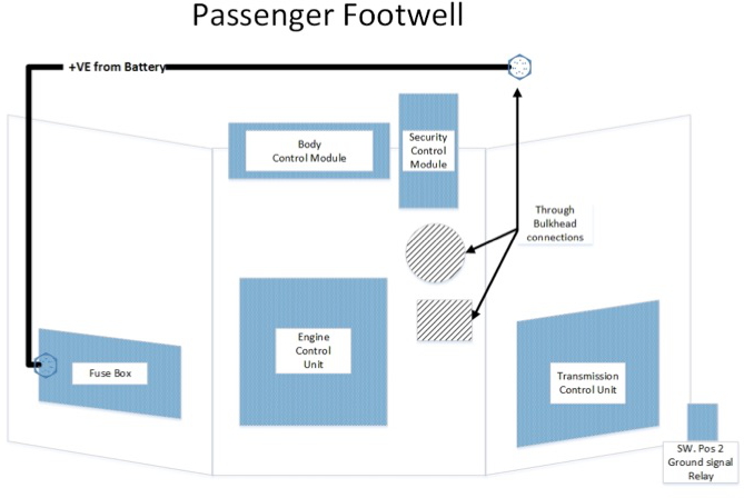
There are a fair few modules that I need to mount somewhere and a lot of wiring that I need to do. I am putting the modules in the passenger foot well. After a lot of thought and trial fitting I have installed the control units as follows.
- ECU vertically where a passengers soles would go. I plan to put a false panel across this area covering/protecting the modules.
- TCU Vertically, to the Right hand side of the foot well
- BCU Horizontally, directly under the battery tray between the bulkhead and the round Fan assembly
- SCU vertically and at an angle between the round Fan assembly and one of the output pipes.
- I also installed one of the XJR Fuse boxes into the left hand side of the foot well behind the door hinges and powered from the through bulkhead bolts used to distribute DC positive power into the interior.
The layout can be seen in the images below:
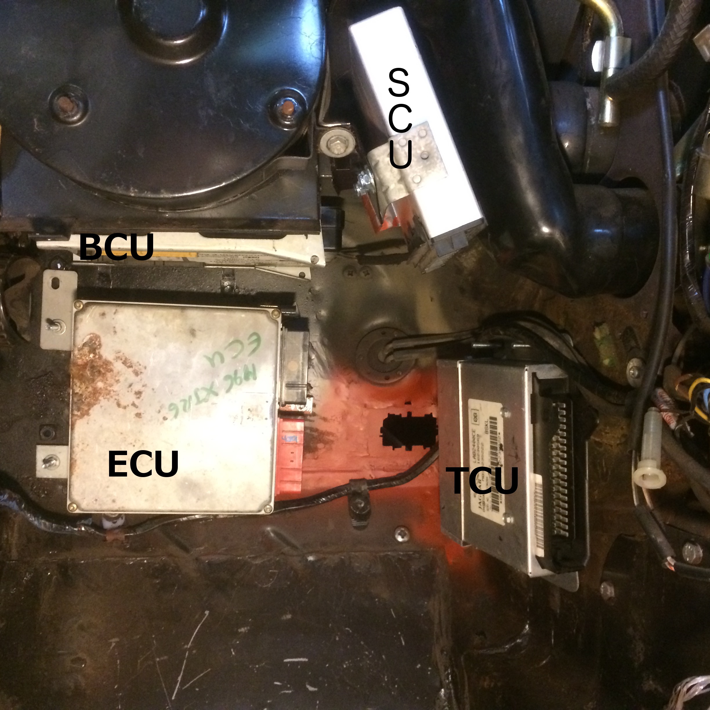
Above, you can see the inserted panel (red paint) with the rectangular hole for the through-bulkhead connector. I had to make quite a complex and accurate hole in the bulkhead to get a good fit for the bulkhead connector as used in the XJR. I should have cut it out of the XJR body but I scrapped the body without thinking about it. It was easier to make up a small panel on the bench with the required cut out and then weld the small square panel into the XJ6 than try to do it upside down in the foot well. The circular item above the red painted area with two pipes in it, is the access point for the Vacuum pipes from the AC unit. That is the hole used for the steering column on a LHD car. I will use it to get the ECU plugs and cables from the engine to the ECU. I will actually have to cut out the outer edge of this factory made hole as the plugs are quite big. There is a rubber gaiter on the XJR loom which should make a nice fit into this hole keeping the engine bay fumes out of the interior of the car. having to make these holes is a shame as I really don’t want to make too many changes to the body as part of this modification.
At least I stayed warm this evening. I hope the weather breaks soon as I have not really done anything to the XJ6 since New Years day. I did work on the XKR regarding the tweeting. I have however, earned some brownie points doing quite a few DIY jobs in the house.